Environmental Engineering Reference
In-Depth Information
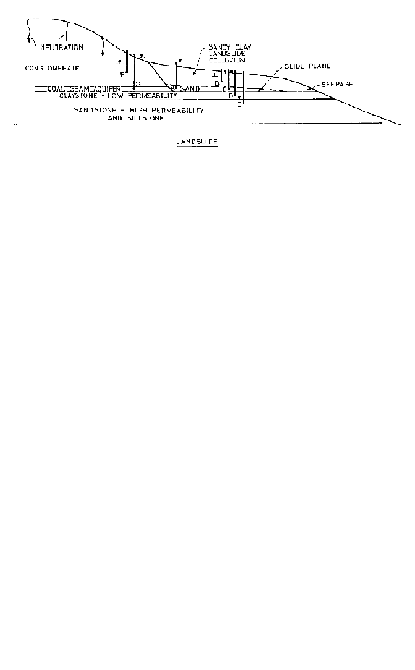
Figure 20.13.
Landslide piezometric conditions.
-A slotted standpipe at B (with pipe extending above ground surface) will rise to the
phreatic surface at E. In this case the pore pressure at B equals the head BE, because the
pore pressure at B is higher than at any other point intersected by the standpipe. If the
standpipe was cut off at the ground surface, water would flow from the pipe;
- It is the pore pressure in the embankment which is critical to stability, not the position
of the phreatic surface. If k
h
/k
v
was only say 4, the equipotentials would be steeper and
the pore pressures for the embankment would be higher for the same phreatic surface.
Hence pore pressures, not the location of the phreatic surface, should be measured.
Landslide.
Figure 20.13 shows piezometric conditions in a landslide. Steady state
piezometric levels are shown for piezometers installed at points A to G.
The following points should be noted:
- The factor of safety against sliding is very sensitive to the pore pressures. From a slope
stability viewpoint it is the pore pressure on the slide plane which is critical, i.e. at A and
C. Piezometers (B) in the landslide colluvium may give different pore pressures;
- Piezometers (D), installed in a borehole drilled into a low permeability layer below the
slide colluvium, should be backfilled with sand past the slide plane, or the response time
for the piezometer will be very slow and pressures different from that on the plane may
be measured;
- If boreholes are extended into a more permeable layer as for piezometer E, low pore
pressures may be measured. If the sand backfill is extended to the slide plane, water
may drain towards the sandstone/siltstone and give lower pressures than actually are
present at the slide plane;
- Piezometers installed in the low permeability conglomerate may take a long time to
reach equilibrium and are likely to show lower piezometric levels than piezometers
installed in the coal seam aquifer (see F and G).
Jointed and sheared rock
.
Figure 20.14
shows a jointed and sheared rock mass into
which a cutting has been excavated. The low permeability shear zone and clay infilled
joint affect the flow of groundwater towards the excavation.
The stability of the cutting is determined by the strength of the joints, bedding planes
and shear zone, which in turn is determined by the water pressure on these features.
If piezometers are installed in boreholes BH1 and BH2 as shown:
- Piezometer PX will read pressure due to phreatic surface C;
- Piezometer PY will read pressure due to phreatic surface B;
- Piezometer PZ will read pressure due to phreatic surface A.