Environmental Engineering Reference
In-Depth Information
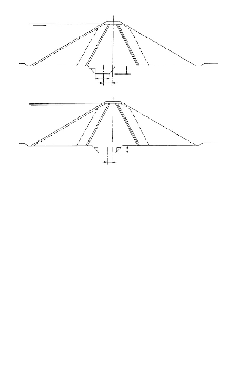
Crest
Cut off
1
h
1
W
(a)
Varies as h varies
Crest
Cut off
1
1
h
11
Fixed distance - say 5 m,
independent of h
(b)
Figure 17.10.
Cutoff trench layout (a) incorrect setout; (b) correct setout.
shows the effect of positioning the trench at the upstream contact of Zone 1 and the foun-
dation. The result is a “footprint” of the cutoff trench which is curved and more difficult
to construct than Figure 17.10b which is positioned relative to the centreline.
The actual width of the base of the trench is best set as a fixed width or widths and nar-
rower up the abutments where the effective height is less.
It should be remembered that the actual depth of the cutoff trench will be determined
by geotechnical factors and is not known accurately before the start of construction. It is
necessary to set out the batter pegs for the excavation based on an assumed depth of exca-
vation. It is wise to be somewhat conservative in doing this, particularly if a minimum
width (3 m) trench is being used, so that it is not necessary to restart excavation from the
surface in the event that the actual depth to cutoff foundation is greater than expected.
17.5
SELECTION OF CUTOFF FOUNDATION CRITERIA FOR
EMBANKMENT DAMS
The selection of cutoff foundation criteria for a project will depend on the particular site
and embankment under construction. The following useful hints assist in this process:
- Never specify a depth of cutoff trench, i.e. depth below general foundation. The
requirements for cutoff are geological and geotechnical and the depth to achieve these
will vary. It is, however, appropriate for the geotechnical engineer/engineering geolo-
gist, in consultation with the embankment designer, to estimate the likely depths as a
guide for the construction personnel.
- Do not specify a weathering grade alone as a requirement to achieve a suitable founda-
tion. The requirements for cutoff foundations are essentially those of permeability and