Environmental Engineering Reference
In-Depth Information
(a)
(b)
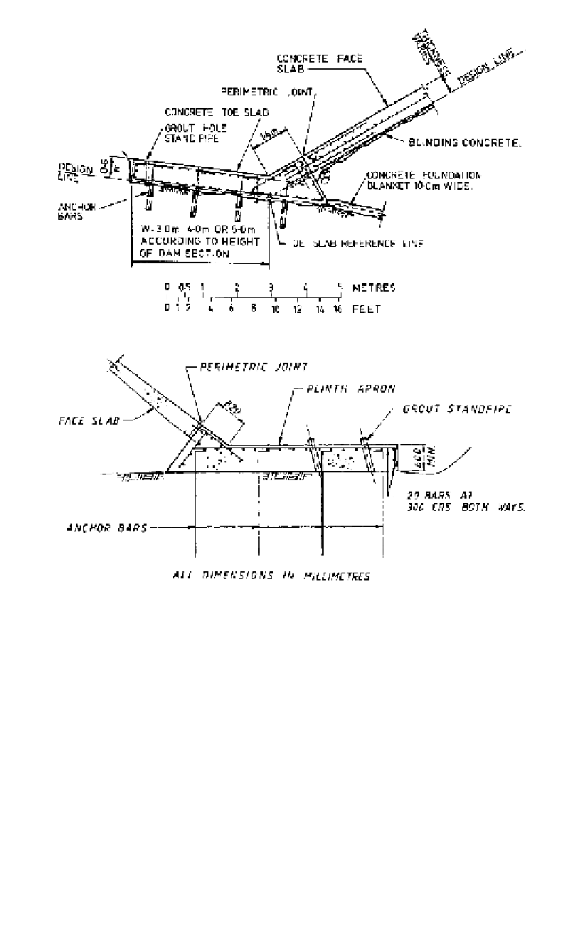
Figure 15.13.
Plinth designs for (a) Mangrove Creek Dam, (b) Boondooma Dam (Mackenzie and
McDonald, 1985; Rogers, 1985, reproduced with permission of ASCE).
near the plinth and finer rockfill compacted in thinner layers may be adopted (Fitzpatrick
et al., 1985). However, one must also be careful not to obtain a modulus significantly
higher than the rockfill or differential settlement may still occur. Some use a Zone 2A as
shown in Figure 15.13 in this area.
To ensure that the face slab displaces normal to its plane, and is not subject to bending,
the Hydro-Electric Commission (Fitzpatrick et al., 1985) require a minimum of 0.9 m of
rockfill under the face slab, see
Figure 15.14
.
The plinth is laid out as a series of straight lines selected to suit the foundation and
topography. The angle points are not related to the vertical joints in the slab, and will be
a compromise between added excavation and face slab thickness and simplicity of con-
struction.
The plinth may be laid out to be horizontal in a section normal to the centreline of the
plinth (as for Cethana Dam, Figure 15.14a), or at right angles to the dam axis (as in Reece,
Figure 15.14b). The latter gives a smaller volume of excavation for the plinth, but concreting