Environmental Engineering Reference
In-Depth Information
Concrete face slab
Perimetric joint
Plinth
Zone 2D
Zone 2E
Zone 3A
Zone 2F
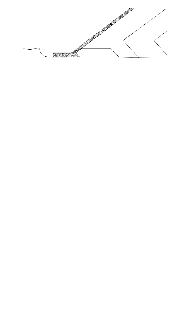
Figure 15.3.
Detail of Plinth area showing Zone 2F.
Zone 2D
. Transition rockfill, processed rockfill or alluvium, grading from silt to cob-
ble size or in more recent dams, from silt to coarse gravel size. The transition provides uni-
form support for the face slab and acts as semi-impervious layer to restrict flow through
the dam in the event that cracking of the faceplate or opening of joints occurs.
Zone 2E
. Fine rockfill, selected fine rock which acts as a filter transition between Zone
2D and Zone 3A in the event of leakage through the dam.
Zone 3A
. Rockfill, quarry run, free draining rockfill placed in layers about 1 m thick.
This zone provides the main support for the face slab and is compacted to a high modu-
lus to limit settlement of the face slab.
Zone 3B
. Coarse rockfill, quarry run, free draining rockfill placed in layers about 1.5
to 2.0 m thick. Larger rock may be pushed to the downstream face. This zone is less
affected by the water load than Zone 3B, so a lower modulus is acceptable. The thicker
layers allow placement of larger rock.
The boundary between Zone 3A and 3B should be selected with care. There has been a
trend to moving the boundary from what is shown in
Figure 15.2
to the dam centreline and
even upstream of the centreline, but Marulanda and Pinto (2000) warn that, at least for
high dams, this may lead to larger settlements.
Zone 2F.
Some modern dams include a Zone 2F filter zone beneath the perimetric joint
as shown in Figure 15.3. This serves two functions: (a) to act as a high modulus zone to
limit deformation of the slab at the perimetric point; (b) to act to limit leakage flow in the
event the joint opens. If a zone of earthfill (Zone 1A) is provided upstream of the slab,
Zone 2F acts as a filter to that earthfill in the event the joint opens and leakage initiates.
Zones 2F is usually a maximum size of 19 mm or 37 mm, with some silty fines, placed
in thin (200 mm) layers.
Many variations of this zoning are adopted to meet site conditions and the quality of con-
struction materials available. As discussed in Section 15.5.1, non free draining rockfill may
be used, provided free draining zones are incorporated to give any seepage water a controlled
path to the dam toe. In some dams, low permeability earthfill is placed upstream of the face
(Zones 1A and 1B in Figure 15.3) to control leakage. This is discussed in Section 15.5.4.
The zone designation discussed above is used throughout the topic. The transition
Zones 2D and 2E have been so designated to differentiate from Zones 2A, 2B and 2C used
in earth and rockfill dams. There is no consistent terminology in use throughout the world.
Many dams include a concrete crest wall which reduces the quantity of rockfill required
(see
Section 15.3.4
)
.
These developments, along with other refinements in design, have resulted in the earlier
problems being overcome and acceptance of CFRD for the construction of many dams,
including dams up to 190 m high. CFRD up to 230 m high are in the design phase.
Table 15.1
and
Figure 15.4
show the trend in design and rockfill compaction of CFRD.
The trends in compaction of rockfill in earth and rockfill dams are included.