Environmental Engineering Reference
In-Depth Information
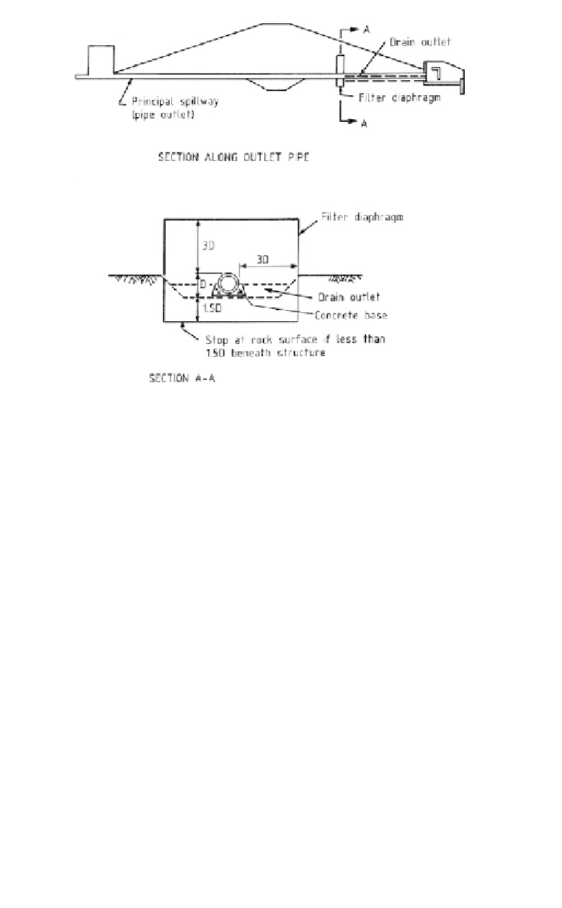
Figure 13.16.
Filter diaphragm for seepage and piping control around outlet pipe (Talbot & Ralston,
1985, reproduced with permission of ASCE).
USBR, Corps of Engineers, FERC, major USA Consulting Companies and the first author,
were unanimous in agreeing that cutoff collars should not be provided because they made
compaction more difficult.
Talbot and Ralston (1985) indicate that the Soil Conservation Service of the USA have
replaced conduit cutoff collars with a filter diaphragm as shown in Figure 13.16.
They indicate that a single diaphragm is constructed around outlet conduits or other
structures in the downstream section of the dam as shown in Figure 13.16. The diaphragm
consists of a graded sand-gravel filter that projects outward a minimum of 3 times its
diameter (for pipes) and extends 1.5 times its diameter below the pipe if the foundation is
soil or erodible weathered rock. Where other embankment or foundation filter drainage
systems are used, the diaphragm must tie into these systems to provide a continuous zone
that intercepts all areas subject to cracking, poor compaction or other anomalies.
The “drain outlet”, is a layer, or layers of sand/gravel designed to act as a filter against
the soil in the embankment and foundation, and with sufficient discharge capacity to
transmit seepage intercepted by the filter diaphragm.
13.5.5
Recommendations
The authors recommend the following:
(a) Where practicable, avoid placing conduits through the dam, or on soil and erodible
rock foundations, by using outlet tunnels in the abutments (for larger dams) or plac-
ing the conduit in a trench excavated into non erodible rock and backfilled with con-
crete as shown in
Figure 13.17(a)
. Avoid deep, partly backfilled trenches, with steep
sides as shown in Figure 13.17(b) because these will become zones of potentially poor
compaction and low stresses conducive to hydraulic fracture and initiation of piping.