Environmental Engineering Reference
In-Depth Information
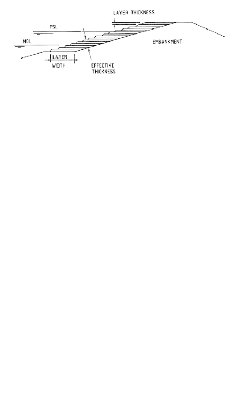
Figure 13.6.
Use of soil-cement for upstream slope protection.
-A wide range of soils can be used but usually clayey sand and/or silty sand with 10% to
25% passing 75 mm. The Plasticity Index is usually less than 8;
- The required cement content is determined by laboratory tests, which include wet-dry
and freeze-thaw durability and unconfined compression strength. The requirements are
detailed in ICOLD (1986d). Freeze-thaw testing would not seem appropriate in many
countries with temperate or tropical climates. The USBR require an unconfined com-
pressive strength of 4.1 MPa at 7 days and 6 MPa at 28 days. For field applications 2%
cement (by weight) additional to that determined in the laboratory is used to allow for
difficulties in mixing and compaction.
Soil-cement has proven to be a satisfactory slope protection over long periods - up to
30 years at least. Readers are directed to ICOLD (1986d) and more recent literature for
additional details on the method.
13.2.2
Downstream slope protection
13.2.2.1
General requirements
The downstream slopes of earth and rockfill and concrete face rockfill dams are formed
by rockfill. For these dams erosion of the face is not an issue and the requirement usually
is simply to provide a uniform surface within the tolerance specified. Where no berms are
provided access to survey markers or other instruments on the downstream face of rock-
fill can be difficult and consideration should be given to providing narrow berms at 30
metre maximum vertical intervals.
It is not unusual for contractors to go to some trouble to sort larger rocks on the down-
stream face to give a pleasing appearance to the dam.
For earthfill dams, the downstream face is potentially erodible and considerable care
needs to be taken to prevent erosion. This is done by:
- Covering the surface with a layer of rockfill or by establishing grass cover;
-Providing berms to limit the vertical distance over which runoff can concentrate;
-Providing lined drains on the berms to catch the runoff and carry it to the abutments;
-Providing open lined drains at the contact between the abutment and the dam as shown
in
Figure 13.7(b)
, or the drains on the berms may be extended along the abutments as
shown in Figure 13.7(a). In both cases erosion at the contact between the embankment
and the abutment is being controlled.
The authors' experience is that berms should be provided at no greater than 10 m ver-
tical intervals, although in arid climates berms may be unnecessary. A berm should
be provided above the outlet of a horizontal drain as shown in
Figures 13.5(a)
and (c).