Environmental Engineering Reference
In-Depth Information
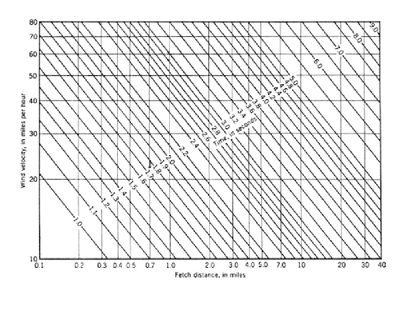
Figure 13.3.
Wave periods (Saville et al., 1962; USBR, 1981).
This equation is valid for most reservoirs where the reservoir is relatively deep com-
pared to the wind generated wave length (i.e. water depth
0.5L). For the normal free-
board computation, the runup should be calculated using the average of the highest 10%
of waves, which is 1.27Hs. For shallow reservoirs it is suggested that US Corps of
Engineers (1984a) or USBR (1992) be used.
13.1.3.4
Wave runup
Runup (Rs) from a significant wave on an embankment with rip-rap surface underlain by
earthfill can be calculated from:
Hs
Rs
(13.3)
0.4
(Hs/L)
0.5
cot
where Rs
runup height in metres; Hs
significant wave height in metres; L
wave-
length in metres;
angle in degrees of upstream face of the dam to the horizontal.
Rockfill dams act like permeable rubble mounds and have a different effect on energy
dissipation from rip-rap placed on an “impervious” earthfill embankment. For these
dams the “relatively permeable rubble mound” curves in
Figure 13.4
should be used.
For smooth impermeable slopes of concrete or soil cement with a water depth at the
dam greater than three times the wave height, the “smooth slope” curves in Figure 13.4
should be used. USBR (1981, 1992) indicate that these curves may underestimate runup
by 15% to 20%.
For waves which are not normal to the dam, a correction should be applied to the com-
puted runup. This is done by multiplying the runup by the cosine of the angle between the
wave propagation direction and a line normal to the dam, provided the angle is less than
about 50°.