Environmental Engineering Reference
In-Depth Information
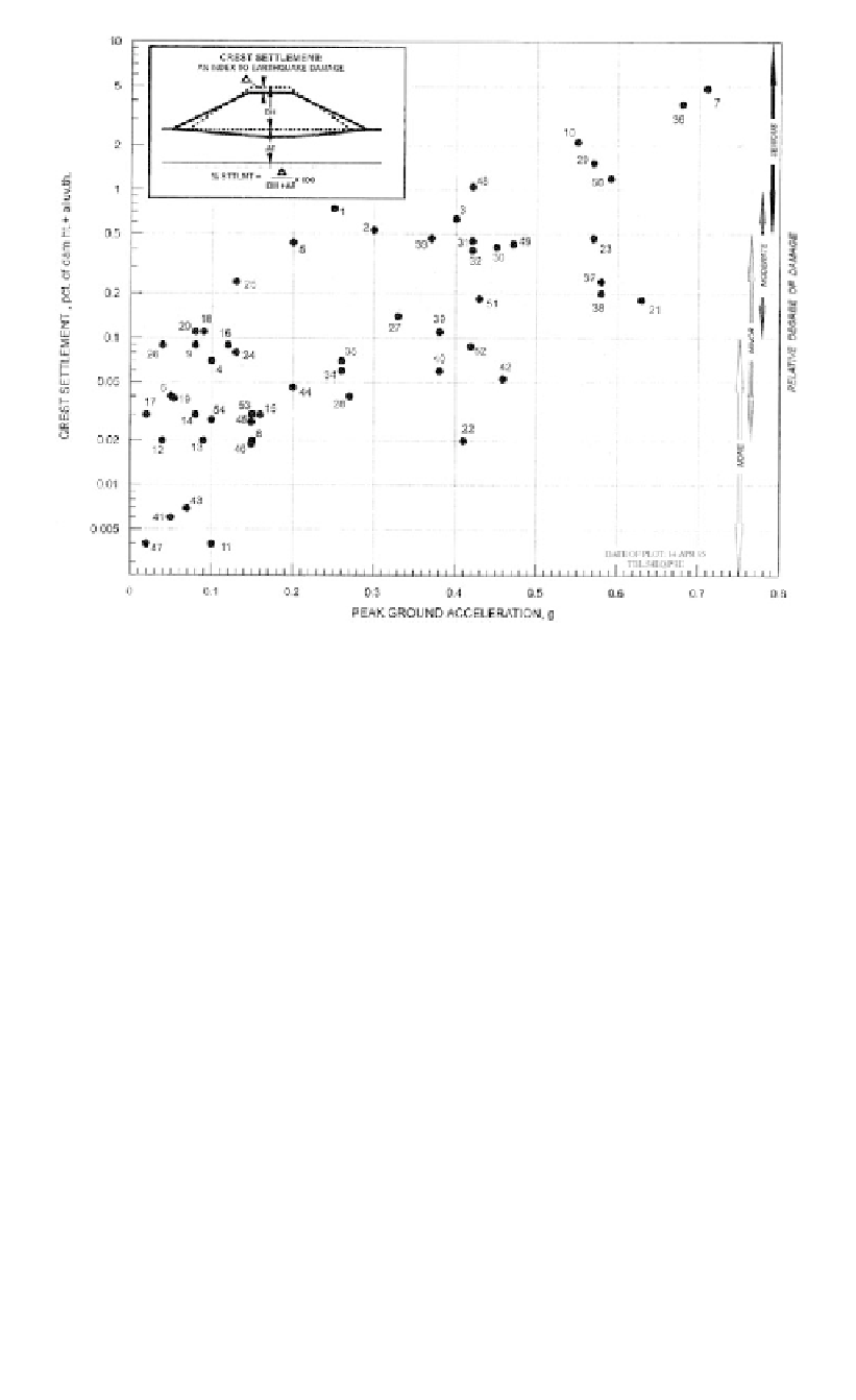
Figure 12.33.
Relative crest settlement versus peak ground acceleration (Swaisgood, 1998).
in which M is the magnitude of the earthquake (M
L
or local magnitude below 6.5, and M
S
or surface wave magnitude at 6.5 or above), and PGA is the peak horizontal ground accel-
eration at the damsite as a fraction of the acceleration due to gravity.
2.0 D
0.35
RF
for earthfill dams
8.0 D
0.35
for hydraulic fill dams
0.12 D
0.61
for rockfill embankments
in which D is the distance between seismic energy source and dam, in kilometres.
This method should only be used to give an approximate estimate of settlements, where
there is no potential for liquefaction or significant strain weakening. Account should be
taken of the scatter in the data as shown in Figure 12.33 and in practice it is probably best
just to use Figure 12.33.
12.6.3.2
Pells and Fell empirical method for estimating settlement, damage and
cracking
Pells and Fell (2002, 2003) gathered data from 305 dams, 95 of which reported cracking,
and classified these for damage according to the system shown in
Table 12.4
.
Figures 12.34
and
12.35
show plots of damage contours versus earthquake magnitude
and peak ground acceleration for earthfill and earth and rockfill dams.
In respect to cracking, Pells and Fell (2003) concluded:
- Earthquakes cause settlement, lateral spreading and cracking of embankment dams. Slope
instability may occur but it is not common. Longitudinal cracks are more common than
transverse cracks and are mostly in the upper part of the dam, more likely on the upstream
face than the downstream.