Environmental Engineering Reference
In-Depth Information
The blast furnace cement has greater resistance to attack by aggressive groundwater (pore
water) which dissolves the free lime in the cement and selenitic water. These result in for-
mation of tricalcium sulpho-aluminates which destroys the hardened grout by expanding.
Alternatively fly ash may be added in proportion 10% to 100% by weight of cement
(ICOLD, 1985).
Retarders are added to the mix to control the curing process mainly to delay the initial set.
The addition of cement, which has free lime (Ca(OH)
2
and/or gypsum (CaSO
4
) to the
bentonite slurry makes it flocculate because of cation exchange of the Ca
ions for Na
ions in the bentonite. The slurry remains stable (i.e. doesn't bleed) but does not form such
an effective filter cake on the sides of the trench as bentonite and hence losses are greater.
Xanthakos (1979) indicates losses may be up to 100% of the trench volume. This
increases costs but gives a greater effective wall width. Admixtures can be used to reduce
the flocculation effect and the use of BLF cement (with less free lime) instead of portland
cement assists.
The cement bentonite grouts commonly have very low strength compared to concrete.
ICOLD (1985) indicate an unconfined compressive strength of 100 kPa at 28 days, 150 kPa
at 90 days. The strength is affected by water/cement ratio and cement type. The grout is able
to withstand considerable plastic deformation to accommodate settlement due to embank-
ment construction. It is best if the cement-bentonite grout has a Youngs Modulus just a lit-
tle larger than the surrounding soil. In this way the load applied by the dam causes the wall
to remain in compression.
10.4.5
Diaphragm wall using rigid or plastic concrete
Diaphragm walls are excavated in alternating panels as shown in Figure 10.19 with the
panel supported by bentonite. The wall is constructed by tremie pipe placement of con-
crete or cement-bentonite concrete (“plastic concrete”).
The ends of each panel are supported by a steel “stop-end” tube as shown in
Figure
10.20
. The pipe is removed after initial set of the concrete leaving a half round key which
is used as a guide for the excavating tool, thus reducing potential misalignment of panels
and leakage.
It should be noted that for dam cutoffs the walls are not usually reinforced with
steel.
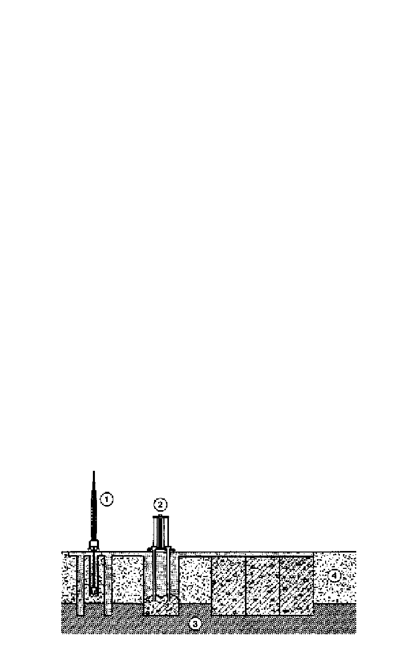
Figure 10.19.
Diaphragm wall cutoff, (1) excavation; (2) concreting; (3) substratum; (4) permeable
layer (ICOLD, 1985).