Environmental Engineering Reference
In-Depth Information
determine the continuing erosion boundary for soils with D
85B
0.1 mm. The test proce-
dures of the CEF tests were essentially the same as those of the NEF test, as described by
Sherard and Dunnigan (1989), but with the following modifications:
-Water passing through the filter during the tests was collected and the eroded materials
dried and weighed to determine the loss of base soil required to seal the filter;
-Progressively coarser filters were used until the filter was not sealed;
- Thicker base specimens were used to allow for greater erosion losses.
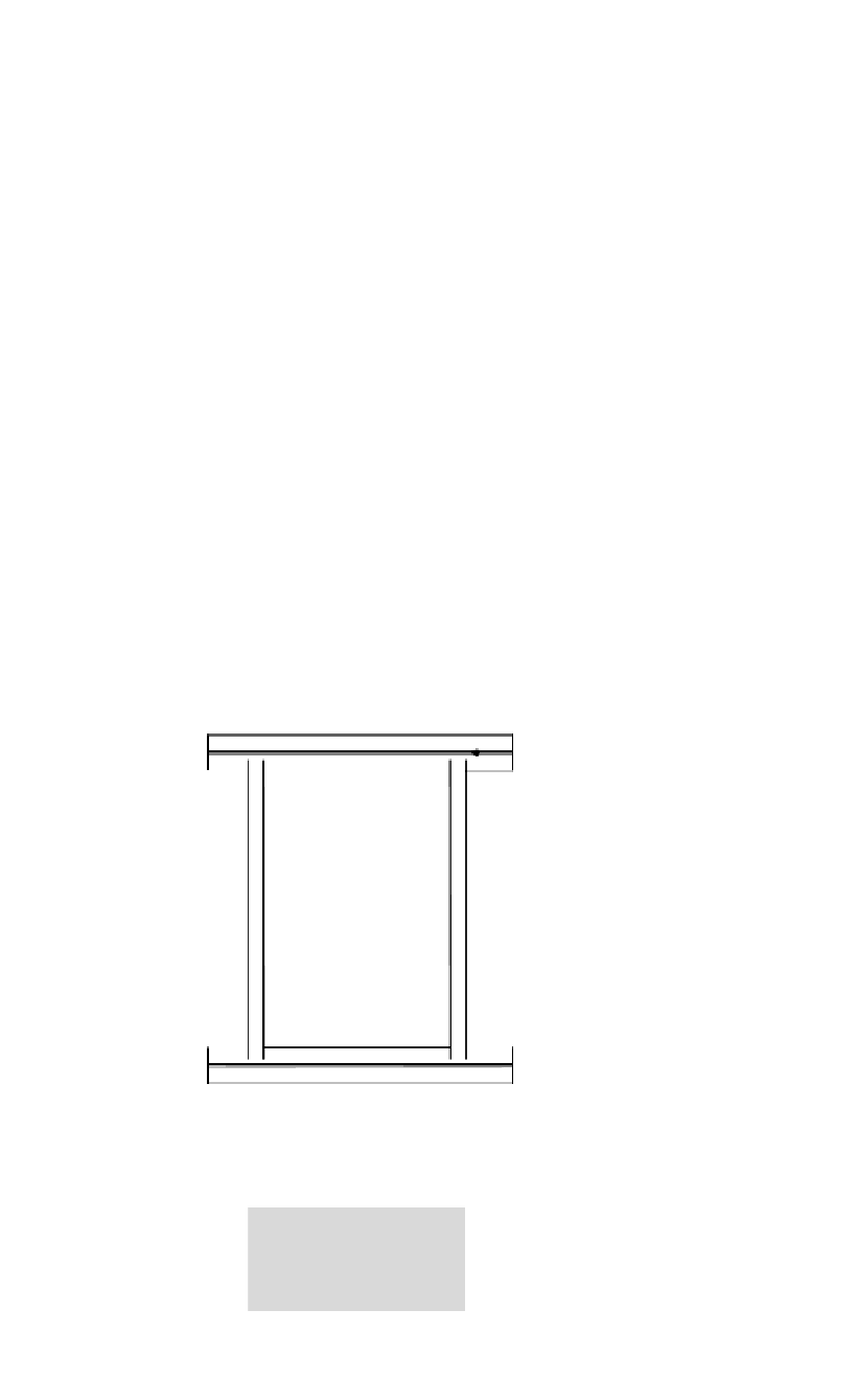
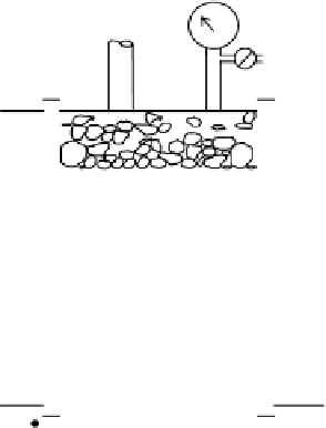
Details of the CEF test setup are shown in Figure 9.21.
The tests were carried out for until it was evident the filter was sealed or it was
judged that the filter was not going to seal no matter how much erosion of the base soil
occurred. The filters were judged to have sealed when all of the following conditions were
reached:
- Full mains pressure was maintained in the space above the base specimen as measured
on the pressure gauge;
-Water passing through the filter was clear;
- The flow rate of water passing through the filter had decreased substantially from the
initial flow and was relatively constant.
From mains
water supply
(240-300kPa)
From mains
Pressure gauge
19 mm dia. inlet pipe
Air vent
Top gravel layer
Preformed hole in base specimen
(1.0 to 2.0 mm dia. for NEF tests
and 5mm for dia. for CEF tests)
125 mm dia.
clinder for
DF15
15 mm
Compacted base specimen
(25 mm thick for NEF tests and
100mm thick for CEF tests)
205 mm dia.
cylinder for
DF15
15 mm
Side material
Filter material
(150 mm thick for DF15
15 mm
200 mm thick for DF15
15 mm)
Bottom drainage layer
Two 19 mm dia. outlet pipes
0.075 mm sieve
Eroded core materials
Plastic drum (s)
Figure 9.21.
Continuing erosion filter test apparatus (Foster and Fell, 1999a, 2001).