Environmental Engineering Reference
In-Depth Information
(a)
(b)
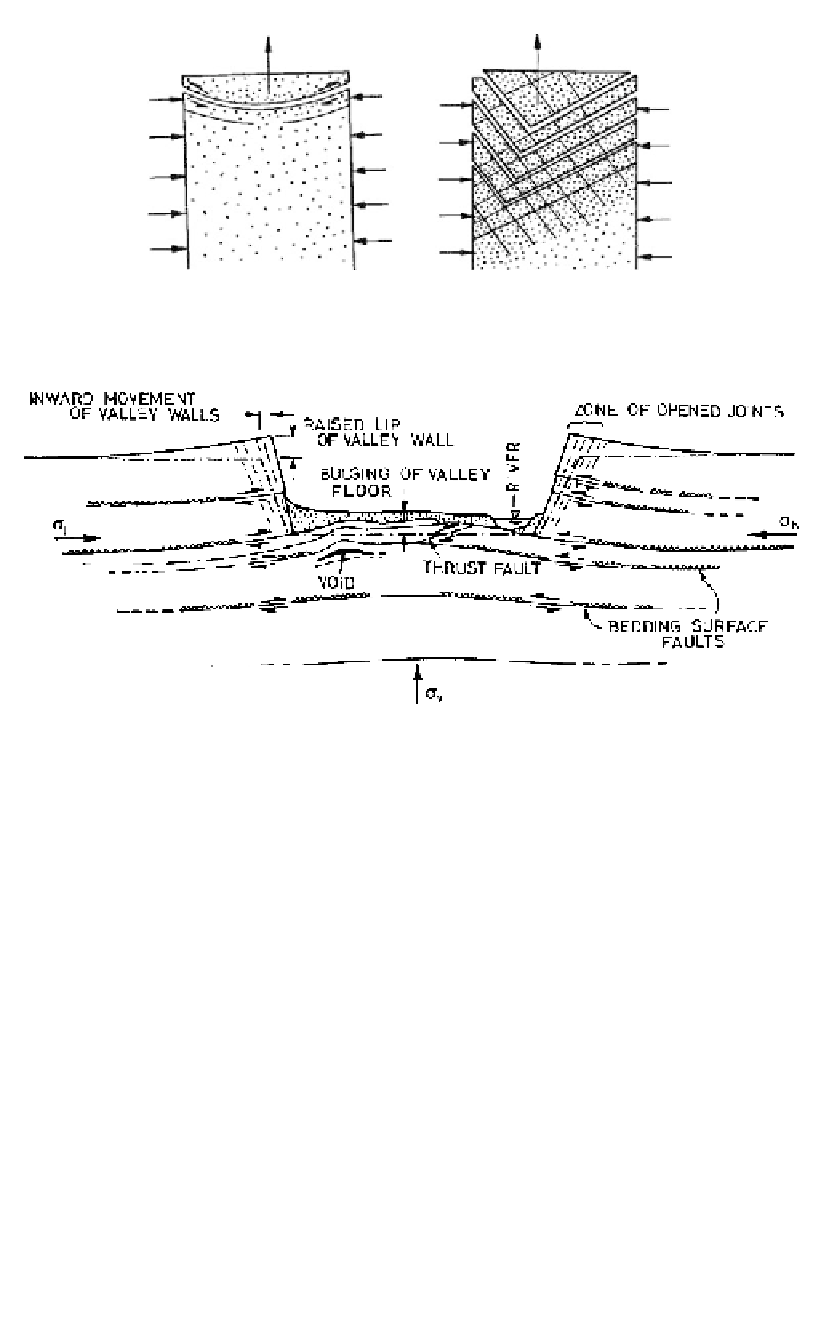
Figure 2.6.
Effects of destressing in (a) intact rock, and (b) jointed rock.
Figure 2.7.
Complex valley structures related to stress release in weak, flat-lying rocks (based on Patton
& Hendron, 1972).
rocks of moderate to low strength. The phenomenon is referred to as “valley bulging” or
“valley rebound”, and has been described by Zaruba (1956), Simmons (1966), Ferguson
(1967), Patton and Hendron (1972), Matheson and Thompson (1973), Horswill and
Horton (1976), McNally (1981) and Hutchinson (1988).
Most of the features shown on Figure 2.7 have clearly developed as a result of buckling
and shear failure under high horizontal compressive stresses. The stresses were concen-
trated beneath the valley floor as a result of load transfer as the excavation of the valley
removed lateral support from the rock layers above the floor, and vertical load from the
rock beneath the floor. The steeply-dipping joints next to the cliff faces probably opened
up due to expansion of the rock layers under the influence of horizontal stresses both
across and parallel to the valley.
All of the effects shown on Figure 2.7 were present at the site for Mangrove Creek Dam
near Gosford, New South Wales. This 80 m high concrete faced rockfill dam is located in
a valley 200 m to 300 m deep, cut through an interbedded sequence of sandstones, silt-
stones and claystones (
Figure 2.8
)
. Away from the river the rock layers in the valley sides
generally show joints at wide to very wide spacings.
Near and beneath the river bed there is a broad, gentle, “valley bulge” as shown on
Figure 2.8. Although the shape of this feature is not very pronounced, the rock within it
was intensely disrupted down to 15 m below the river bed. The sandstone unit E (
Figure