Environmental Engineering Reference
In-Depth Information
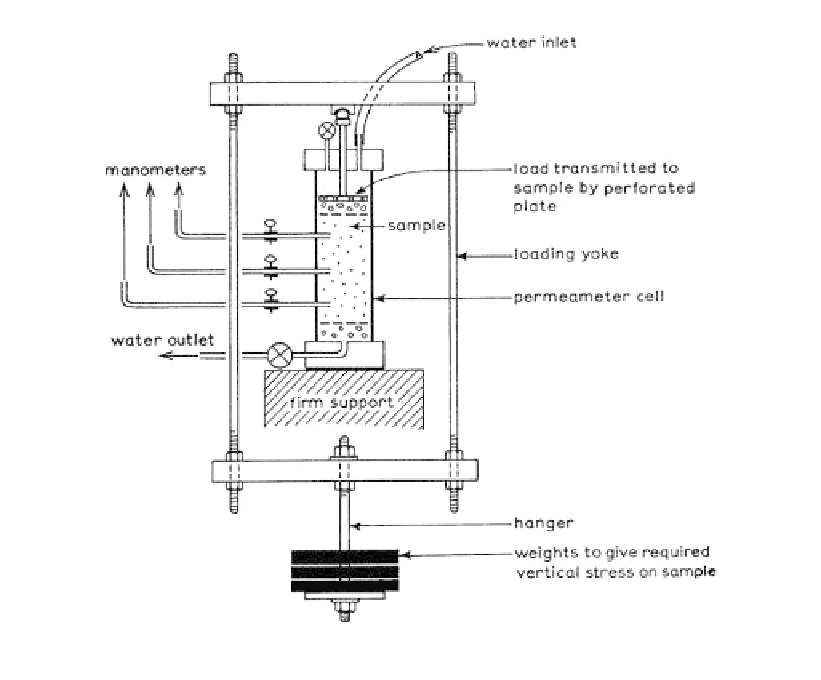
Figure 6.55.
Suitable assembly for constant head permeability apparatus (Head, 1985).
(c) failure to saturate sample;
(d) failure to adequately test the fabric of the soil;
(e) testing under little or no confining stress. For dams work in particular it is important
to use apparatus such as that shown in Figure 6.55 which allows simulation of the
overburden pressure on the soil and in so doing allows testing at the correct void
ratio;
(f) excessive flow rates in the apparatus (when testing in coarse sand or gravel) leading to
unaccounted losses in the pipework or porous plates at the ends of the sample and an
underestimation of permeability.
From the above, (a) and (c) can be eliminated by careful test procedures; (b) is to be
expected and requires several tests so that variability can be identified; and (d) can be
overcome by correct sampling, using larger samples and/or using in-situ tests. Problems
with high flow rates (f) can be readily checked by testing the apparatus without soil.
6.3.3
Indirect test methods
6.3.3.1
Oedometer and triaxial consolidation test
For “very low” to “semi impermeable” clays, it is often more accurate to estimate the per-
meability from the results of oedometer consolidation tests, rather than to carry out
falling head tests. From the theory of consolidation:
k
c m
wv v
(6.46)