Java Reference
In-Depth Information
ControllerInterface
Runnable
void openPump(String
name, int percent)
void run()
Pump
Tank inputTank
Tank outputTank
int outFlow
TankController
PumpInterface
void setOutputFlow
(int percent)
int tankLevel
String tankState
TankInterface tank
PumpInterface pumpA
PumpInterface pumpB
void setOutput
Flow()
void flush()
Tank
void setMode()
void openPump(...)
void run()
TankInterface
int getLevel()
double color[]
int capacity
int level
int getLevel()
void push()
void pull()
MixerController
ControllerInterface redController
ControllerInterface greenController
ControllerInterface blueController
void run()
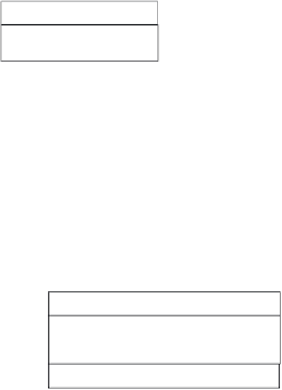
Figure 13.11
The class diagram of Prototype 2
As we have described in the previous section, the PLCs behave like finite
state automata, whose state transitions fire when the paint level of a colour
tank or mixer tank reaches the values of predefined thresholds. This means
that the PLCs should measure the current paint level of the tanks continu-
ously. This approach is consistent with the mechanism used to get state
information from a physical device.
13.5.3
Implementation
The implementation of the second prototype requires the transformation of
the work cell simulator into a remote application in order to allow the PLCs
to exchange data and commands with the simulated devices via the internet.
Since we decided to use Java RMI for the interconnection of remote objects,
we have to define the interfaces exported by the
Tank
and the
Pump
classes,
i.e.
TankInterface
and
PumpInterface
. These interfaces indicate which
methods can be invoked by a remote application. Then, we modify the
declaration of class
Tank
and class
Pump
so as to extend the basic class
UnicastRemoteObject
. Their constructors should declare that they throw
java.rmi.RemoteException
. Finally, class
Simulator
registers the device objects
with unique names using the
java.rmi.Naming
class.