Java Reference
In-Depth Information
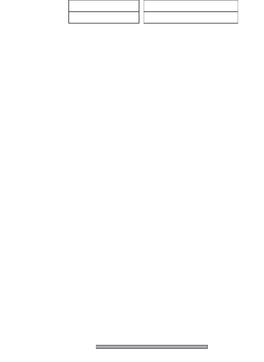
TankInterface
PumpInterface
int getLevel()
void setOutputFlow(int percent)
Figure 13.4
The interfaces of two physical devices
has a well-defined communication interface. Similarly, we simulate the
behaviour of the physical devices by implementing objects that export well-
defined interfaces. Basically, a PLC needs to access the value of the current
level of paint in a tank and to set the output flow of a pump. Figure 13.4
shows the UML definition of the tank and pump interfaces.
The equipment of the car painting work cell is physically distributed over
a wide area. Groups of closely connected devices (e.g. a tank and the
input
output pumps) are controlled by dedicated PLCs that run on net-
worked computers physically located in proximity to the equipment. In
order to facilitate the transition from the simulated prototype to the real
system, the design of the simulator's architecture must take into account the
distributed nature of the manufacturing work cell.
Decision point
Simulator architecture: centralized or distributed?
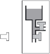
A first design solution consists in simulating the behaviour of each device
or group of devices as part of the behaviour of the PLC that controls their
functioning (Figure 13.5). This solution has a major drawback: the physical
constraints that characterize the paint flow between two tanks should be
enforced through the exchange of data between the corresponding PLCs.
This approach requires defining two different implementations of each PLC
for the control of the simulated work cell and of the real work cell, making
the results of the test cases performed in simulation useless.
A second design solution consists in simulating each physical device or
group of devices as independent applications that run on dedicated com-
puters connected to the PLCs through the network. The result is a fully
distributed simulator.
PLC
PLC
PLC
PLC
Figure 13.5
The symbiosis between simulated devices and PLCs