Java Reference
In-Depth Information
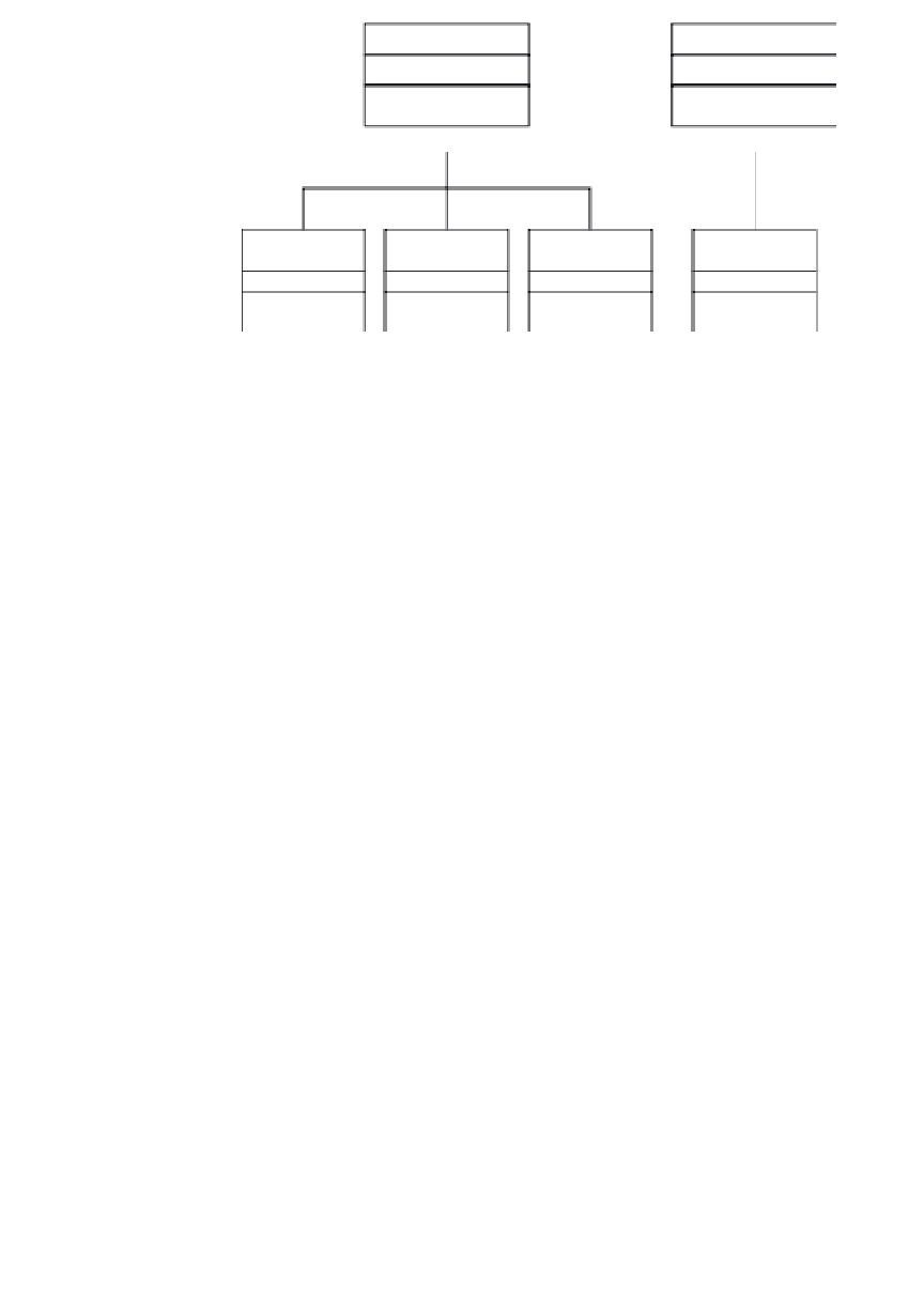
Robot
Environment
Platform
Sonar
Laser
Obstacle
Figure 10.8
The analysis diagram
expressed by a pair of
x
,
y
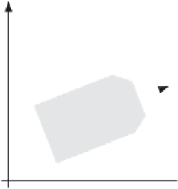
Cartesian coordinates related to the environment's
reference frame. The description of each obstacle is loaded from an XML file.
At this stage we are mainly interested in the geometric representation of
the robot, not in its dynamic behaviour and control. The robot is made up of
a mobile platform, a telemeter device and a ring of sonar devices. For each
component we define a class. Class
Robot
plays the role of integrator of the
robot's devices.
Class
Platform
represents the mobile platform that is made up of a rectan-
gular base, four wheels and two motors. For the sake of simplicity we do not
model the individual components. The mobile platform occupies a place in
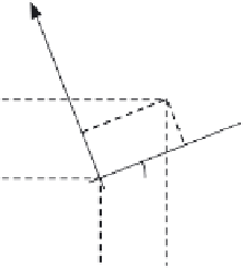
the environment and can change its position. This requires defining a
geometric shape that delimits the robot's physical boundaries. We introduce
a robot reference frame that is co-located with the robot. The origin of this
reference frame coincides with the middle point of the rear wheels' axis (see
right-hand side of Figure 10.9). The
x
-axis coincides with the forward move-
ment direction. Thus, the robot's position in the environment is described
Y
V
x
v
x
'
cos(R
t
)
v
y
'
sin(R
t
)
R
x
y
V
y
v
x
'
sin(R
t
)
v
y
'
cos(R
t
)
R
y
Equation 10.1
Global coordinates
V
V
y
x
R
x'
R
x
d
x
'
cos(R
t
)
v
y
R
y'
R
y
d
x
'
sin(R
t
)
R
t
v
x
R
y
Equation 10.2
Straight translation
R
t
'
R
t
d
t
Equation 10.3
Rotation
R
x
V
x
X
Figure 10.9
The geometric relations between the robot and the environment
reference frames