Biomedical Engineering Reference
In-Depth Information
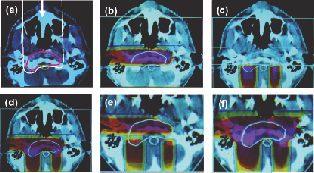
To meet this problem a technique of “field patching” has been
developed. Figure 11.12 shows an example of this method. In this
example, a lateral beam (Figure 11.12b) is combined with a pair of
posterior “patch” beams (Figure 11.12c). The composite dose
distribution (Figure 11.12c) shows an elevated dose in the junction
region. The problem of patching is highlighted when one looks at the
uncertainty analysis and sees the potential for either hot or cold spots
in the plan (Figures 11.12d and 11.12e). For this reason, the posterior
patches are in practice feathered, as described above.
Figure 11.12. Example of patched proton beams used to treat a horse-
shoe shaped target volume (CTV): (a) outline of a possible anterior
field which, however, would be contraindicated due to inhomogeneities;
(b) lateral field; (c) pair of posterior patched fields; (d) composite plan;
(e) lower bound dose distribution; and (f) upper bound dose distribution.
Patched fields are, in fact, early examples of intensity-modulated
radiation therapy in that each individual field irradiates the target
volume non-uniformly.
Intensity-modulated proton therapy
Passive scattering is a mature approach which offers a simple and
effective method of delivering proton therapy. For a single field
direction, passive scattering can provide excellent conformation of
dose to the distal end of the target and good conformation laterally.
However, due to the fixed depth-modulation of Bragg peaks across
the whole field, it neither can provide conformation of the dose to the