Information Technology Reference
In-Depth Information
It is possible to capture 3D Holoscopic images electronically using an image
sensor. This form of capture requires a high resolution image sensor together with
specialised optical components to record the micro-images fields produced by pre-
cision micro-optics (see figure 3). The two-tier system shown in figure 2 has been
used for the capture of the 3D holoscopic images used in this work. The ob-
ject/scene is recorded on a film placed behind the recording microlens array
through a rectangular aperture. The recorded data is then scanned using a high
resolution scanner. The aperture greatly affects the characteristics of the micro-
images recorded. Since each micro-image is an image of the object seen through
the aperture independently, its shape and size is determined by the aperture. If the
field of a sub-image is fully covered by the image, it is said to be
fully-filled
, oth-
erwise it is said to be
under-filled
or
over-filled
.
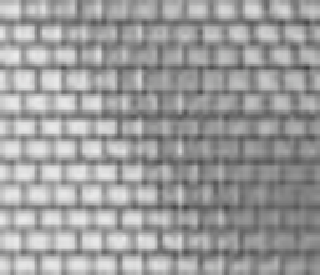
The system will record live images in a regular block pixel pattern. The planar
intensity distribution representing a 3D holoscopic image is comprised of 2D array
of M
M micro-images due to the structure of the microlens array used in the cap-
ture and replay. The resulting 3D images are termed omnidirection 3D holoscopic
images and have parallax in all directions. The rectangular aperture at the front of
the camera and the regular structure of the hexagonal microlenses array used in
the hexagonal grid (recording microlens array) gives rise to a regular 'brick struc-
ture' in the intensity distribution as illustrated in Figure 4.
×
(a)
(b)
Fig. 4
(a) Example of the nature of sub-image field. (b) Magnified section.
Unidirectional 3D holoscopic images are obtained by using a special case of the
3D holoscopic imaging system where 1D cylindrical microlens array is used for
capture and replay instead of a 2D array of microlenses. The resulting images con-
tain parallax in the horizontal direction only. Figure 5(a) shows an electronically
captured unidirectional 3D holoscopic image and figure 5(b) shows a magnified
section of the image. The M vertically running bands present in the planar inten-
sity distribution captured by the 3D Holoscopic imaging camera are due to the
regular structure of the 1D cylindrical microlens array used in the capture process.