Information Technology Reference
In-Depth Information
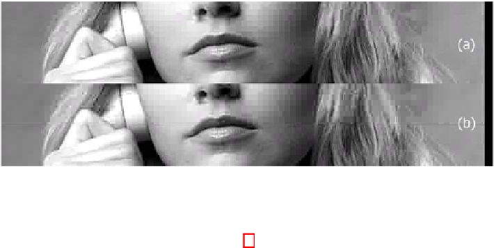
Fig. 5
Output image with and without our shift and padding function
signals that have five blank lines. In Fig. 4 (a), such 1080-HDSDI signals has been
input to the encoding module directly without the video shift and padding function,
causing boundary mismatch to occur between the edge of the image and the DCT
block. These mismatches appear not only at the top of the active image and also
at its bottom. In Fig. 4 (a), the hatched areas representing the output of the SHR
projector mean that the lines degraded in the video quality. However, in Fig. 4 (b),
our encoder has received a 1035-HD signal using the conventional 1080-HDSDI
system, and has shifted and padded the input image to prevent the coding distortion
mentioned above. In the example in Fig. 4 (b), the shift and padding function cannot
prevent the two mismatches from occurring, which appear at the top and bottom
of the active image at the same time. This is because “1030” is not a multiple of
eight. To make the distortion noise caused by mismatch inconspicuous, the video
shift size has been determined to prevent the mismatch border from being allocated
to the center of SHR image, and to copy the top and bottom lines of the image data
onto the non-image data area. The decoder system does nothing in regard to this
operation because the copied data are aborted later. There are examples of output
images with and without our function in Figs. 5 (a) and (b). Figure 5 (b) indicates
that the video quality is not satisfactory because many viewers may recognize the
horizontal center line caused by the mismatch of the image boundary and DCT block
boundary as previously mentioned. However, it is difficult to find such a line in
Fig. 5 (a). These results demonstrate that video shift and padding prevent image
quality from degrading around the center of the frame because the image border
matches the DCT block.
4
Switchable Cascade Multiplexing Function
Our system is equipped with a switchable cascade multiplexing function to increase
its flexibility in the multiplexing mode. This function of our encoder system is out-
lined in Fig. 6.
The basic concept behind this function is to mix TS packets from two packet
queues, i.e., internal and external queues. The internal queue stores the packets