Information Technology Reference
In-Depth Information
3.1 Video Format Converter
To encode SHV signals in the Y/Cb/Cr format, the original SHV signals should first
be converted for ease of handling. The video format converter converts the
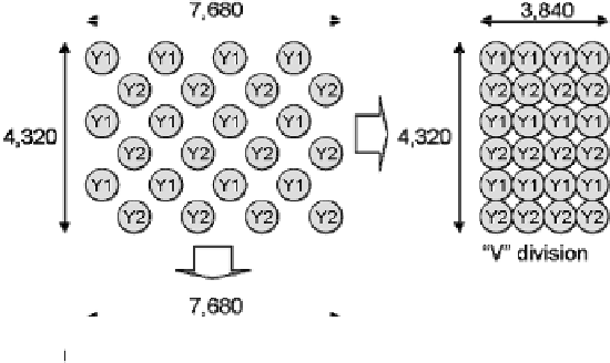
7,680×4,320 (G1, G2, B and R) format from/into sixteen 1,920×1,080/30 Psf (progres-
sive segmented frame) (Y/Cb/Cr 4:2:2) HDTV size images, where the SHV images
are divided spatio-temporally. The color format conversion is shown in formula (3.1),
which is based on ITU-R BT. 709. As previously mentioned, the current SHV signals
are formatted by the pixel-offset method. Each signal component (G1, G2, B, and R) is
a quarter of the size of an SHV signal and is arranged in a pixel shift position as shown
in Figure 1. Since there are two luminance signals Y1 and Y2 after the video format
conversion, the number of meaningful pixels becomes equal to half the SHV total area
of 7,680×4,320. Therefore, in the case of conversion to the 16 HD-SDI (high defini-
tion serial digital interface) signals in practice, SHV signals should be spatially divided
into 8 parts and temporally into 2 parts. Spatial division should have two modes: (a)
four horizontal parts and two vertical parts (“H” division) and (b) two horizontal parts
and four vertical parts (“V” division), as shown in Figure 4. The final spatial division
is shown in Figure 5 and temporal division is shown in Figure 6. A diagram of the total
codec system including the video format converter is shown in Figure 7.
Y
1
0
7152
0
0
0722
0
2126
G
1
⎡
⎤
⎡
⎤
⎡
⎤
⎢
⎥
⎢
⎥
⎢
⎥
Y
2
0
0
7152
0
0722
0
2126
G
2
⎢
⎥
⎢
⎥
⎢
⎥
=
(3.1)
⎢
Cb
⎥
⎢
−
0
1927
−
0
1927
0
5000
−
0
1146
⎥
⎢
B
⎥
⎢
⎥
⎢
⎥
⎢
⎥
Cr
−
0
2271
−
0
2271
−
0
0458
0
5000
R
⎣
⎦
⎣
⎦
⎣
⎦
Fig. 4
Spatial division modes