Civil Engineering Reference
In-Depth Information
Heat-Pipe-Based PV/T
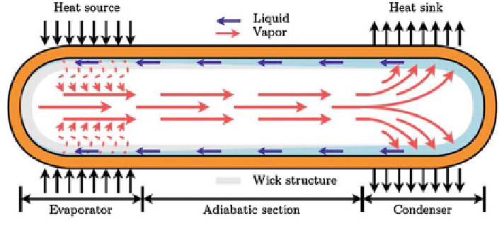
Heat pipes are considered efficient heat transfer mechanisms that combine the
principles of both thermal conductivity and phase transition. A typical heat pipe, as
indicated in Fig.
9
, consists of three sections, including evaporated section
(evaporator), adiabatic section and condensed section (condenser), and provides an
ideal solution for heat removal and transmission.
PV/heat pipe combination has been recently studied. Zhao et al. (
2008
,
2009
,
2010
) proposed a PV/flat-plate heat pipes array for co-generation of electricity and
hot air/water. This prototype module comprises a photovoltaic layer and a flat-
plate heat pipe containing numerous micro-channel arrays acting as the evapora-
tion section of the heat pipes. The other end of the heat pipe is the condensation
section which releases heat to the passing fluid, and the fluid within the section is
condensed owing to the heat discharge. He claimed that the flat-plate geometry is
more efficient due to the excellent thermal contact between the PV cells and heat
extraction devices, which results in a smaller thermal resistance and higher overall
solar conversion efficiency. In this way, the PV efficiency could increase by
15-30 % compared to the sole PVs, if its surface temperature is controlled to
around 40-50 C. The overall solar conversion efficiency of the module was
around 40 %. Figures
10
and
11
show schematically three types of PV/heat pipe
modules acting as the thermal and power co-generation units.
Qian et al. (
2008
,
2010
) brought forward a new concept for building integrated
PV/T system (IPVTS) utilizing oscillating heat pipe. This system is designed as
the façade-assembled components to transport heat from the concealed PV cells
(OHP-BIPV/T), as shown in Fig.
12
. The system consists of the oscillating heat
pipes, headers, finned tube, graphite conductive layer, metal frame, PV laminate
module and insulations. When in operation, the working fluid within the metal heat
pipes will absorb heat from the PV cells and be evaporated into vapour fluid. The
vapour will flow up into the finned tube where it is condensed by releasing heat to
the passing fluid and returns back to the absorber by effect of gravity and capillary
forces.
Fig. 9
Schematic of a conventional heat pipe (Zhang et al.
2012
)