Civil Engineering Reference
In-Depth Information
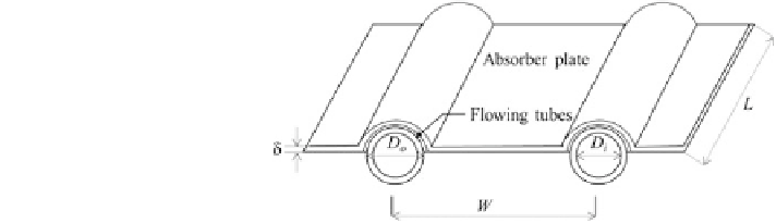
Fig. 4 Schematic of an
absorber plate showing the
various dimensions (Zhang
et al.
2012
)
Hence, the heat collected by the flat-plate PV/T collector could be revised by
the fluid inlet temperature
Q
e
Q
u
¼
F
R
A
c
I s
ðÞ
U
L
T
fi
T
a
ð
5
Þ
where F
R
is the heat-removal factor which is connected with the efficiency factor
(F
0
) using the following equation:
1
exp
U
L
F
0
IC
p
F
R
F
0
¼
IC
p
ð
6
Þ
U
L
F
0
where F
0
varies with different types of working mediums (e.g. water or air)
1
=
U
L
F
0
¼
h
i
for water
ð
7
Þ
1
U
L
D
o
þ
W
D
o
þ
C
b
þ
1
pD
i
h
wm
W
½
ð
Þ
F
1
1
þ
U
L
=
h
wm
A
=
A
c
þ
F
0
¼
h
i
for air
ð
8
Þ
1
1
=
h
r
þ
1
=
h
wm
ð
Þ
where W is the distance between tubes; D
o
and D
i
are the outside and inside
diameter of flow tubes; C
b
is the conductance of the bond between the fin and tube;
h
wm
is the heat transfer coefficient of working medium; A/A
c
is the ratio of heat
transfer area to collector aperture area; h
r
is the equivalent radiation coefficient;
F is the fin efficiency, which could be given by
p
U
L
=
kd
W
D
o
2
F
¼
tanh
ð
Þ
p
U
L
=
kd
ð
9
Þ
W
D
o
2
ð
Þ
where k is the thermal conductivity of the fin and d is the fin thickness.
Electrical Efficiency of the PV Modules (g
e
)
It is known that the electrical efficiency of the PV module decreases with the
increase in the cells' working temperature and this dependence can usually be
written as (Duffle and Beckman
1991
)
g
e
¼
g
rc
1
b
PV
T
PV
T
rc
½
ð
Þ
ð
10
Þ