Civil Engineering Reference
In-Depth Information
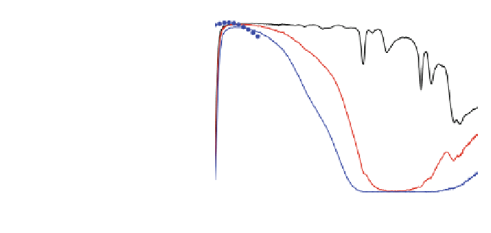
Fig. 13 Spectral
transmittance for
ITO-containing
(PEI-SiO
2
):(LiTFSI)
electrolytes as measured
(curves) and calculated
(symbols). From Bayrak
Pehlivan et al. (
2012b
)
100
80
60
0wt% exp
1wt% exp
1wt% calc
3wt% exp
3wt% calc
5wt% exp
5wt% calc
7wt% exp
7wt% calc
40
20
0
500
1000
1500
2000
2500
Wavelength (nm)
transmittance minimum develops in the near infrared when the ITO content is
increased, whereas the luminous transmittance is almost unchanged (Bayrak
Pehlivan et al.
2012b
). For 7 wt % of ITO, one finds T
lum
= 83.3 % and
T
sol
= 56.3 %, while the electrolyte remains practically free from haze. The
experimental properties can be understood in considerable detail from calcula-
tions, which is a consequence of the accurate theoretical model that exists for
heavily doped wide band-gap oxides such as ITO and its Zn- and Sn-based
alternatives. We note, in passing, that thermochromic VO
2
-based nanoparticles
would be able to transmit more energy at low temperature than at high temperature
(Li et al.
2010
,
2011
,
2012a
), which in principle could lead to additional control of
the solar energy throughput of an electrochromic glazing; these possibilities have
not yet been explored in detail, though.
3 Electrochromic Devices
3.1 Several Challenges
The technology underlying electrochromic glazings involves several steps, and
some of these lie outside the mainstream of today's industrial practice. Clearly, all
these steps must be mastered for successful devices, and failing on one means
failing on the end result. A list of six ''critical'' procedures has been given by
Granqvist (
2008a
) as follows:
Firstly, the electrochromic and counter-electrode films shown in Fig.
2
must be
nanoporous and uniform over large surfaces. There are several ways to accomplish
this, as touched upon in
Sects. 2.1
,
2.2
and discussed in more detail elsewhere
(Granqvist
2012b
,
2013c
). Reactive DC magnetron sputtering at pressures higher
than those typical for metallization may be a preferred technique (cf. Fig.
8
)
(Granqvist
2008b
).