Civil Engineering Reference
In-Depth Information
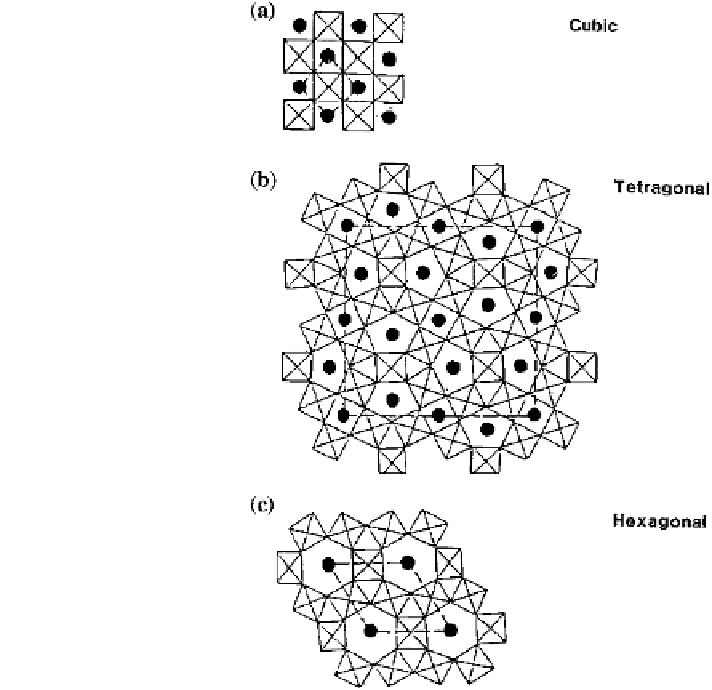
Fig. 6 Structures
representing W oxide with
the shown structures. Dots
indicate sites for ion insertion
in open spaces between WO
6
octahedra. Dashed lines
signify extents of the unit
cells. From Granqvist (
1995
)
spaces between the octahedral units are larger than for the cubic structure, as
indicated in Fig.
6
b. Hexagonal structures, which are delineated in Fig.
6
c, seem
to be formed easily in thin films (Granqvist
1995
), and then, the structure is even
better for ion transport.
The actual nanostructures in thin films of W oxide have been studied several
times, and Fig.
7
reports data based on modeling of X-ray scattering from samples
made by evaporation onto substrates at different temperatures (Nanba and Yasui
1989
). A cluster-type structure is apparent with hexagonal-like units that grow and
interconnect at sufficiently high substrate temperatures.
The relationship between nanostructure and thin-film deposition parameters can
often be well illustrated through ''zone diagrams,'' which have been reported for
different deposition techniques and with different degrees of detail. Figure
8
shows
a ''Thornton diagram'' for the particular case of sputter deposition (Thornton
1974
); more elaborate versions can be found elsewhere (Barna and Adamik
1998
;
Anders
2010
). It is evident that low substrate temperatures and high pressures in
the discharge plasma for the sputtering lead to nanoporous structures of a kind that