Civil Engineering Reference
In-Depth Information
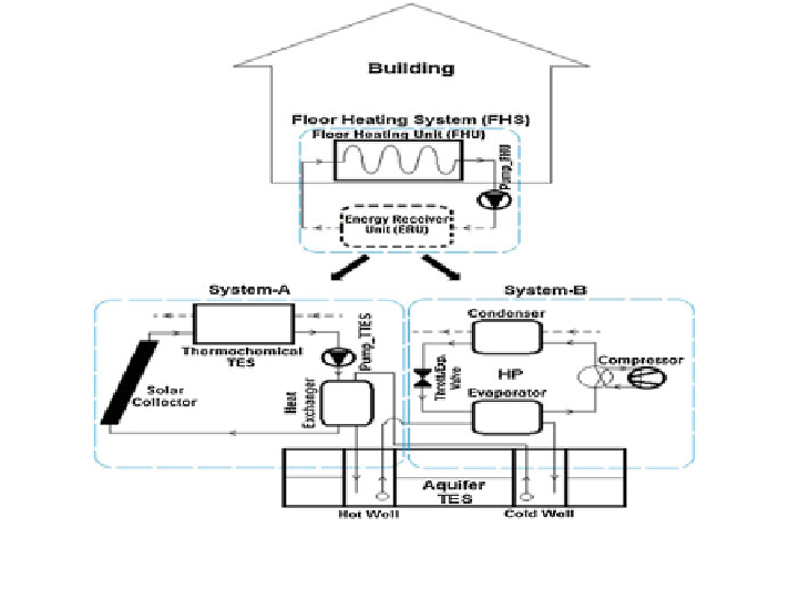
Fig. 12 Schematic layout of the combined thermochemical and sensible thermal energy storage
systems for building heating applications (Caliskan et al.
2012
)
through the water loop; thereby the charging or dehydration of the reactive salt
component of the thermochemical storage system occurs.
The water vapour in the reactor of the thermochemical storage system gets
condensed and subsequently evaporated. Thus, the evaporated water vapour gets
mixed with the concentrated salt; thereby the salt adsorbs the vapour and gets
unsaturated with the release of stored heat energy (discharging or dehydration
process).
This reversible chemical reaction helps the water entering from the building
floor heating loop to the thermochemical heat storage system to gain the stored
heat
energy
for
achieving
effective
energy
redistribution
in
buildings.
The
chemical reaction taking place in the proposed system is given below
SrBr
2
6H
2
O
þ
Heat
!
SrBr
2
H
2
O
þ
5H
2
O
ð
charging process
Þ
ð
5
Þ
SrBr
2
H
2
O
þ
5H
2
O
!
SrBr
2
6H
2
O
þ
Heat
ð
discharging process
Þ
ð
6
Þ
During the charging and discharging processes, the reactive components' H
2
O
is in vapour phase, while SrBr
2
H
2
O and SrBr
2
6H
2
O are in the solid phase.
It is interesting to note that, simultaneous charging of the hot well of aquifer
system as well as the offsetting of heating load demand in the building are
achieved by this system. On the other hand, if the heat energy stored is insufficient
to cater the load demand, the combined system is tuned in such a way that System-
B is engaged to solve the purpose.