Agriculture Reference
In-Depth Information
2. Main line:
PVC pipes of 125 mm in diameter (OD) to convey the water from
the source to the main control points in the field.
3. Sub-main lines:
PVC pipes of 75 mm diameter (OD) were connected to with
the main line through a control unit consists of a 2” ball valve and pressure
gauges.
4. Manifold lines:
PVC pipes of 40 mm in diameter (OD) were connected to the
sub main line through control valves 1.5.”
5.
Distributor subsystem:
• Emitters:
These emitters (GR) were built of PE tubes: 16 mm in diameter
(OD) and 50 m in length. Emitter discharge was 4 lph at 1.0 bar operating
pressure, and the emitter spacing was 50 cm.
• Bubblers:
PE tube 8 mm diameter (OD), with discharge of 40 lph at 0.15
bar operating pressure. These tubes were connected to PVC pipes 32 mm
in diameter (OD) and 50 m in length. The head was adjusted by steel stand
of 180 cm in height and 50 cm diameter. These were in the ring pattern.
The spacing between bubblers was 2 m.
• Discharge
was 4.0 m
3
/h. Distance between gates was 3 m, at 0.15 bar pres-
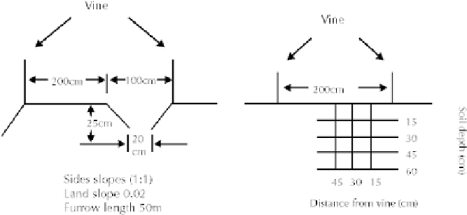
sure. Water flow in furrows was at 1 °Cm from vine. The furrow dimen-
sions were: 10 °Cm width, and 25 cm depth, 1:1 side slopes and bed slope
of 0.01 with flow direction as shown in Fig. 3.
FIGURE 3
Furrow dimensions and sampling locations for the irrigation systems.
20.2.2 MATHEMATICAL EQUATIONS FOR IRRIGATION REQUIREMENTS
Table 5 indicates irrigation efficiencies for this chapter. Irrigation requirements for
grapevines were calculated from the following equation [80].
IR=[(ETo
×
Kc
×
Kr
×
A/Ei) + lR]
×
[I]
(5)
where: IR = irrigation water requirements, liter/tree/interval; ETo = reference evapo-
transpiration, mm/day; Kc = crop coefficient for grape; Kr = reduction factor due to
ground cover; A = ground area per tree, m
2
; Ei = irrigation system efficiency in %;
LR= leaching requirements = (EC
iw
/EC
dw
) × 100, and I = time interval, days.


Search WWH ::

Custom Search