Information Technology Reference
In-Depth Information
C
R
VDD
Signal
V Out
+
EMFi
Output
VSS
Ground
Ground
VDD
EMFi
R
1
V
OUT
+
C
R
2
Output
V
IN
VSS
Ground
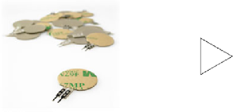
Fig. 1.
On the left, EMFIT S-Series. On the right, Charge Amplifier for EMFIT. Below,
voltage divider to get the EMFi transducer capacity.
3 Design and Implementation of EMFi Based Occupancy
Sensor
3.1 Design of the Sensor Device
The low-power sensor device consists of two functional blocks: a quasi-passive
force change detector and an active occupancy sensor, by means of weight
measuring.
The force change detector design is based on the schematics proposed by the
EMFIT manufacturer for dynamic forces measuring [11]. This schematics use
the sensory model in which the transducer behave as a charge source which is
dependant of the force applied between it's faces. The circuit shown in Figure 1 is
a charge amplifier which transforms the signal transducer into a voltage signal.
The output of this assembly is proportional to the variation of the pressure
supported by the transducer. This signal is then threshold to generate interrupts
to the micro-controller, thereby acting as a detector of changes in weight, with
low power consumption.
The second block, the occupancy sensor, employs the EMFi transducer with
it's model as a force dependant capacitor. Transducer's capacity is measured by
means of a capacitive voltage divider. As shown in Figure 1, the voltage divider
is feed with an AC signal when a measure is to be sampled. The resulting output
is a signal with the same frequency but amplitude-modulated by the force on the


Search WWH ::

Custom Search