Geoscience Reference
In-Depth Information
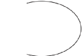
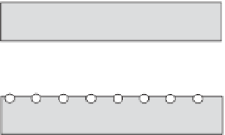
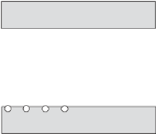
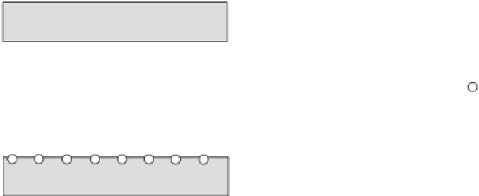
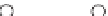
Figure 1.10
Sketch of the charge
distribution and flow regime in a single
pore. The grey areas correspond to the
solid phase. There are four end members
to consider depending on the pore size
with respect to the double layer thickness
and depending on the frequency.
a)
Thick
double layer (the counterions of the
diffuse layer are uniformly distributed
in the pore space).
b)
Thin double layer
(the thickness of the diffuse layer is much
smaller than the size of the pores).
c)
Viscous laminar flow regime occurring
at low frequencies.
d)
Inertial laminar
flow regime occurring at high
frequencies (Modified from Revil
& Mahardika, 2013).
(a)
(b)
(c)
(d)
the inertial flow regime. This regime occurs for Reynolds
numbers higher than 1 but smaller than the critical
Reynolds number corresponding to turbulent flow (typ-
ically 200
permeability of the porous material, and
p
denotes the
pore fluid (mechanical) pressure. Therefore, the stream-
ing current density can be given by
300). For a broad range of porous media, the
effective charge density,
Q
V
, can be related directly to the
permeability,
k
0
, as shown in Figure 1.11. This relation-
ship is very useful to compute or invert the seismoelectric
data since it offers a key relationship between the param-
eter that is controlling the seismoelectric coupling (as
shown later) and the key hydraulic parameter of porous
media, namely, the permeability.
The macroscopic source current density can be
expressed directly as a function of the pore pressure gra-
dient using Darcy
-
Q
0
V
k
0
η
f
∇
J
S
=
−
p
1 80
A popular alternative that can be derived by volume
averaging the Nernst
-
Planck equation is the macroscopic
Helmholtz
-
Smoluchowski equation. For the streaming
current density,
it
takes
the following form (e.g.,
Pride, 1994):
J
S
=
ε
ζ
η
f
F
∇
s law. This law can be seen as a consti-
tutive equation for the flow of the pore water at the scale
of a representative elementary volume or can be seen as a
macroscopic momentum conservation equation for the
pore fluid. It is given by (Darcy, 1856)
'
f
p
1 81
where
F
is called the electrical formation factor (dimen-
sionless) and corresponds to a parameter that is properly
defined in the modeling of the electrical conductivity of
porous media (see Section 1.3). Equation (1.81) assumes
a thin electrical double layer with respect to the size of the
pores, while Equation (1.80) does not require such an
assumption. A comparison between the two equations
shows that the salinity dependence of
Q
V
should be the
k
0
η
f
∇
w
=
−
p
1 79
where
η
f
denotes the dynamic viscosity of the pore
water (in Pa s),
k
0
(in m
2
) denotes the low-frequency