Biology Reference
In-Depth Information
Figure 2.
Illustration of the MFC array and its assembly steps. (A) Illustration of 24-well microbial
fuel cell (MFC) array. Composed of an anode layer (1: anode electrode layer, 2: anode well layer),
a proton exchange membrane (3: PEM), and a cathode layer (4: cathode well layer, 5: cathode
electrode layer). (B)-(F) Microbial fuel cell array assembly. (B) Individual layers of the MFC array:
acrylic support frames (1 and 2), cathode layer (3), anode electrode substrate (4), anode well layer
(5 sandwiched by 6). (C) Assembly of the acrylic frame (1) with the cathode layer (3), followed by
cathode solution loading. (D) Anode well layer and PEM assembly followed by microbe loading.
(E) A fully assembled MFC array with the anode electrode layer (4) and acrylic frame (2) capping
the anode wells. (F) Fully assembled MFC array connected to load resistors and a data acquisition
system. (G) An MFC array device with no acrylic frame.
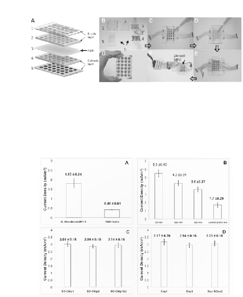
Figure 3.
Characterization of current generated by
S. oneidensis
MR-1 in an MFC array.
(A) Current
densities generated by
S. oneidensis
MR-1 with PBS as the cathode solution at 350 min, TSB
medium was used as the negative control (n = 4). (B) Repeatability of current densities generated
by
S. oneidensis
MR-1 with ferricyanide as the cathode solution at different times after loading. TSB
medium was used as the negative control (n = 5). (C) Chip-to-chip repeatability of current densities
generated by
S. oneidensis
MR-1 with ferricyanide (100 mM) as the cathode solution at 1,000 min
(n = 4 for each chip). (D) Batch-to-batch repeatability of current densities generated by
S. oneidensis
MR-1 with ferricyanide (100 mM) as the cathode solution at 1,000 min (n = 8 for each day). Means
and standard errors were indicated above the bars (mean ± SE).