Image Processing Reference
In-Depth Information
FIGURE 7.2: 3-D digital space and 26N [115]. Left: A 3-cell and its corre-
sponding grid point. Right: Three pairs of α-adjacent 3-cells for α ∈{0,1,2},
α ∈ {0,1}, and α = 0 (from left to right). The 3-cells in each of these three
pairs are connected in 26N.
G
yz
, G
zx
, and G
xy
, such that
G
yz
={ .
...,l
x
(j −g,k−g),l
x
(j,k−g),l
x
(j + g,k−g),...
...,l
x
(j −g,k),l
x
(j,k),l
x
(j + g,k),...
...,l
x
(j −g,k + g),l
x
(j,k + g),l
x
(j + g,k + g),...
.
}⊂ Z
3
.
Similarly, G
zx
and G
xy
can be represented in terms of l
y
and l
z
for a grid
size g ∈ Z
+
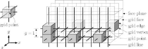
. Here, l
x
(j,k) = {(x,j,k) : x ∈ R}, l
y
(i,k) = {(i,y,k) : y ∈ R},
and l
z
(i,j) = {(i,j,z) : z ∈ R} denote the grid lines (Fig. 7.2) along x-
, y-, and z-axes, respectively, where i, j, and k are integral multiples of g.
The three orthogonal lines l
x
(j,k), l
y
(i,k), and l
z
(i,j) intersect at the point
(i,j,k) ∈ Z
3
, which is called a grid point; a shift of (±0.5g,±0.5g,±0.5g) with
respect to a grid point designates a grid vertex, and a pair of adjacent grid
vertices defines a grid edge [115] (Fig. 7.2).
A grid, as defined above, is characterized by several elements. These are
shown in Fig. 7.2 and explained next. A unit grid cube (UGC) is a (closed)
cube of length g whose vertices are grid vertices, edges constituted by grid
edges, and faces constituted by grid faces. Each face of a UGC lies on a face
plane (henceforth referred as a UGC-face), which is parallel to one of three
coordinate planes. Clearly, each face plane, containing coplanar UGC-faces, is
at a distance of an integer multiple of g from its parallel coordinate plane. A
UGC-face, f
k
, has two adjacent UGCs, U
1
and U
2
, such that f
k
= U
1
∩U
2
.
The interior of a UGC is the open cubical region lying strictly inside the UGC.
A smaller (larger) value of g implies a denser (sparser) grid. For g = 1, the
grid G essentially corresponds to Z
3
. As each grid point p is equivalent to a