Image Processing Reference
In-Depth Information
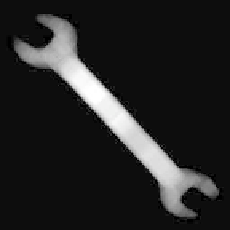
(a)
(b)
(c)
(d)
(e)
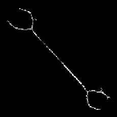
(f)
FIGURE 6.9: Computation of RCMD and thinned pattern: (a) spaner, (b)
the MAT using {112}, (c) count array showing the number of medial disks
covering a pixel, the number being proportional to intensity values, (d) the
RCMD, (e) the set of redundant centers of maximal disks, and (f) skeleton of
the object.
declared redundant and removed from the list of medial circles. Subsequently,
the count array is updated by decreasing the counts of pixels lying within the
redundant circle. The process continues till all the medial circles are tested.
For retaining medial circles of larger radii in preference to the smaller ones,
the testing of redundancy is carried out with the circles in the increasing order
of their radii. A typical result on the computation of the RCMD is shown in
Fig. 6.9.
6.3 Skeletonization Using MAT
In Chapter 1 (refer to Section 1.4.1) we discussed skeletonization of the
binary pattern, which is the process of obtaining skeletal representation of
an object consisting of a set of points forming the spine of the object. The