Graphics Reference
In-Depth Information
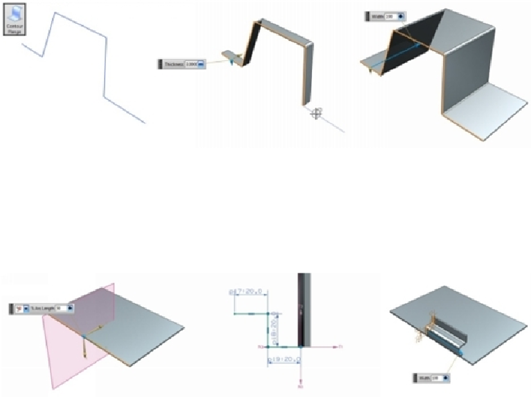
Contour Flange
The contour flange is another basic type of sheet metal feature. In order to create a contour
flange, you need to have an open sketch. Activate the
Contour Flange
command (click
Home > Bend > Contour Flange
on the ribbon) and click on elements of an open sketch.
Drag the arrow or type-in a value in the
Width
box to define the width of the contour flange.
Press Enter to create the contour flange feature.
You can also add contour flanges to a base tab. Activate the
Contour Flange
command and
click an edge of the
Tab
feature. A plane appears normal to the selected edge. Type-in a
value in the
% Arc Length
box and click
OK
to start a sketch. Draw an open profile of
the contour flange feature and click
Finish
on the ribbon. You will notice a contour flange
preview. On the
Contour Flange
dialog, select
Width > Width Option > Finite
to define a
finite distance of the contour flange.
Select
Width Option > Symmetric
to create the contour flange on both sides of the profile.
Select
Width Option > To End
to create the contour flange upto the end of the selected
edge.