Environmental Engineering Reference
In-Depth Information
1
2
3
4
5
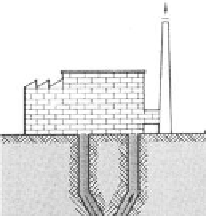
FIGURE 5.11
Constant pressure CAES reservoir with compensating water column. (1) Exhaust. (2) CAES
plant. (3) Surface pond. (4) Stored air. (5) Water column. (From O. Weber, Air-storage gas tur-
bine power station At Huntorf,
Brown Boveri Review
, 62: 332, 1975.)
would need to be addressed [56]. Since pressure compensated operation
cannot be employed in aquifer systems, the use of constant-pressure CAES
operation is limited to systems with reservoirs mined from hard rock.
Cavern Size
The energy storage density of CAES (depicted in Figure 5.12) depends on the
maximum reservoir pressure, the storage volume operational mode, and the
storage pressure ratio (see the appendix at the end of this chapter for deriva-
tion of relevant storage density equations). For all three cases considered in the
appendix, the electric energy storage density E
GEN
/V
S
increases approximately
linearly with increasing reservoir pressure p
S2
(or equivalently with mass per
unit volume p
S2
* M
W
/RT
S2
). In some cases however, this may result in large heat
loss in the aftercooler, depending on the thermal constraints of the cavern [65].
The use of a constant-pressure compensated cavern requires the smallest
cavern by far. Zaugg estimates for a configuration similar to the Huntorf
design (with a storage pressure of 60 bar) that a constant pressure cavern
could deliver the same output with only 23% of the storage volume required
for a constant volume configuration with variable inlet pressure (p
S2
/
p
S1
= 1.4) [33]. If hard rock reservoirs are unavailable or too costly, pressure