Environmental Engineering Reference
In-Depth Information
• A 220 Vac and 120 Vac circuit breaker panel for protection and power
routing to user loads
• A system control, monitoring, and user interface panel that regu-
lates and controls the entire system
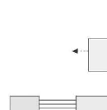
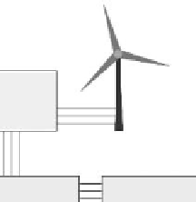
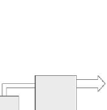
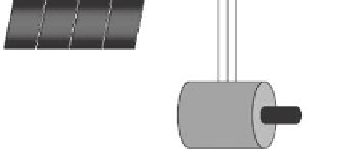
Figure 4.9 shows a block diagram of the connections of an example electrical
system. All the components introduced above and shown in the figure are
described in more detail below. In reality, a system would likely only have
one local renewable energy source (solar panels or wind turbines). Also, it is
possible that this system could be run off the grid, but emergency back-up
power provisions such as batteries may be required. In general, the func-
tional components (with the exception of the system controller) are avail-
able commercially. Further detailed engineering design work is required
to correctly interface and control these components in a concerted and safe
manner.
Wind Turbine
Wind
Turbine
Interface
To system
controller
60 Hz
220 Vac
220 Vac
120Vac
Circuit
Breaker
Panel
60 Hz
480 Vac
480 Vac Circuit
Breaker Panel
220 Vac-120 Vac
Transformer
To Loads
480V
Utility
Meter
60 Hz
480 Vac
60 Hz
120 Vac
To system
controller
Grid Tie Inverter
with Rectifier
System Control,
Monitoring, and
User Interface
Solar
Power
Controller
600 Vdc
Motor Drive/
Generator Excitor
Rectifier
To solar
controller
To wind turbine
controller
PV Solar Array
Aquifer UPHS
Motor-Generator
FIGURE 4.9
Electrical system block diagram.