Biomedical Engineering Reference
In-Depth Information
T12
Case 1
Case 2
Case 3
Normal
L1
L2
L3
L4
L5
S1
Pelvis
-1
0
1
2
3
4
Displacement (mm)
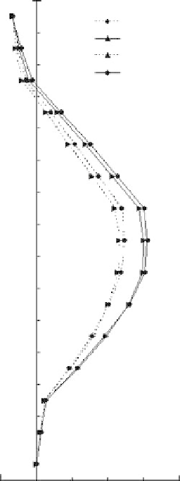
FIgure 15.5
Curved plot of spine deformation in the sagittal plane for the FOVVM. The points between
every two vertebrae represent intervertebral discs.
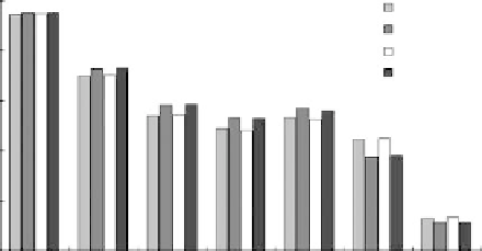
5
Normal
Case 1
Case 2
Case 3
4
3
2
1
0
T12
L1
L2
L3
L4
L5
S1
FIgure 15.6
The vertical deformation of the vertebrae for the FOVVM.
shows a curved plot of spine deformation in the sagittal plane for the FOVVM and the marked points
indicate the vertebrae and intervertebral discs. Figure 15.6 exhibits the deformations in the vertical
direction. From Figures 15.4 and 15.6, it can be seen that the human upper body primarily under-
goes vertical vibration with little motion in the A-P direction during WBV. Figure 15.7 indicates the
rotational angles, in the sagittal plane, of each vertebra for the FOVVM. From the figures, it can be
seen that the lumbar spine segments not only show vertical vibration but also exhibit A-P motions
Search WWH ::

Custom Search