Biomedical Engineering Reference
In-Depth Information
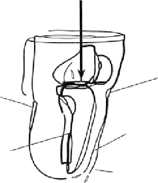
Force application based
on gait analysis data
Patella tendon
Popliteal
depression
Residual limb
Bones
Prosthetic liner
(fixed boundary)
FIgure 13.1
Assembled prosthetic liner, residual limb, and bones in the finite element model. There are
overlappings at the patellar tendon and popliteal depression regions.
socket, based on a loose plaster cast of the limb surface. The bones and the limb surfaces were iden-
tified and segmented using MIMICS software (Materialise, Inc., Leuven, Belgium).
The unrectified cast, representing the residual limb surface, was digitized using the BioSculptor
TM
system and exported to the computer-aided design (CAD) software ShapeMaker
TM
(Seattle Limb
System). This shape was modified into a soft liner placed within a hard patellar tendon-bearing
(PTB) socket. A rectification template (Radcliff and Foort, 1961) was applied onto this shape by
adding buildups at pressure-sensitive areas and undercuts at pressure-tolerant areas to prepare the
inner surface of the prosthetic liner.
The surfaces of the bones, residual limb, and prosthetic liner were imported to SolidWorks 2001
(SolidWorks Corporation, Massachusetts). Assembling of the liner, limb, and bones was performed
based on the relative positions among the three structures. Positions of the bones relative to the
residual limb surface were based on the same set of MRI scans. The position of the shape-modified
prosthetic liner relative to the residual limb surface was based on the outputs from Shapemaker
TM
,
in which the prosthetic liner was produced by adding buildups and undercuts directly to appropriate
regions of the residual limb model. The assembled liner, limb, and bones are shown in Figure 13.1.
It can be seen in the figure that there were some overlapping areas at the interface where socket
undercuts were made.
The surfaces were then converted into solid models using SolidWorks. The soft tissue model
was generated by geometrically subtracting the bones from the solid limb. The prosthetic liner was
given a thickness of 4 mm. The solid models representing bones, soft tissues, and liner were then
imported to the finite element package ABAQUS (Hibbitt, Karlsson & Sorensen, Inc., Pawtucket,
Rhode Island). An FE mesh with a total of 22,301 three-dimensional tetrahedral elements was built
using ABAQUS automeshing techniques. The meshed geometries of the residual limb, prosthetic
liner, and bones are shown in Figure 13.2.
13.2.2 m
aterial
p
ropertieS
The material properties were assumed to be linearly elastic, isotropic, and homogeneous. Young's
modulus was 200 kPa for soft tissues and 10 GPa for bones. Poisson's ratio was assumed to be
0.49 for soft tissues and 0.3 for bones (Zhang and Lord, 1995). The prosthetic liner was assigned a
Young's modulus of 380 kMPa and Poisson's ratio of 0.39, resembling the mechanical properties
of pelite.
Search WWH ::

Custom Search