Biomedical Engineering Reference
In-Depth Information
5
o
10
o
(a)
(b)
(c)
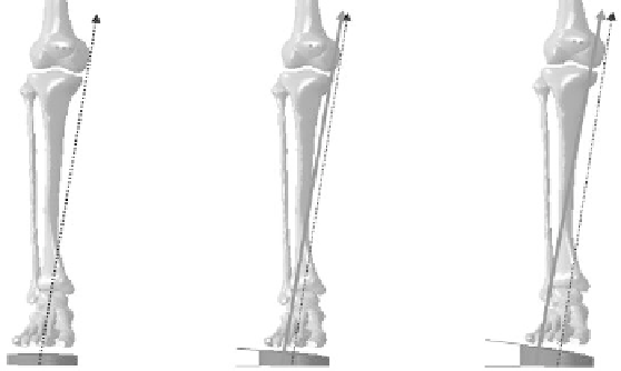
FIgure 12.1
The lateral-medial shift of the center of pressure and the ground reaction force (GRF) direc-
tions in the frontal plane with orthoses at (a) 0-degree, (b) 5-degree, and (c) 10-degree wedge angles. The
blocks beneath the feet represent orthoses at three wedge angles. The directions of the GRF in wedge condi-
tions are shown by arrows in the solid blue line. The GRF in the flat orthosis condition is the control, shown
as a dotted arrow in (b) and (c). The dashed line represents the lever arm of the GRF, which passes through
the center of the knee joint.
coordinates of a dynamic musculoskeletal model toward a desired kinematic trajectory. The calcu-
lated muscle forces were later input to the FE model together with gait analysis data to investigate
the internal loadings of the knee joint under different orthotic interventions.
12.3.2 f
inite
e
lement
m
odelinG
of
tHe
f
oot
-a
nkle
-k
nee
c
omplex
and
o
rtHoSiS
The subject who was involved in the gait analysis also volunteered for magnetic resonance (MR)
scanning of the right lower extremity. The MR images were scanned in a neutral unloaded position.
The images were segmented using MIMICS v14 (Materialise, Inc., Leuven, Belgium) to obtain the
boundaries of the skeleton and skin surface. After reconstruction from two-dimensional images, the
three-dimensional objects generated were required to go through several steps before being imported
to the FE software. Rapidform XOR3 (INUS Technology, Inc., Seoul, South Korea) was used to con-
vert surface models to solid models. The models generated were then imported into ABAQUS v6.11
(Dassault Systems Simulia Corp., Providence, Rhode Island) for FE modeling and analysis.
The FE model of the human foot-ankle-knee complex (Figure 12.2) consisted of 30 bony
segments, including the distal segment of the femur, patella, tibia, fibula, and 26 foot bones. All
the bony and ligamentous structures in the foot and ankle region were embedded in a volume of
soft tissue. In the knee joint, the menisci, articular cartilages, anterior cruciate ligament (ACL),
posterior cruciate ligament (PCL), medial collateral ligament (MCL), and lateral collateral ligament
(LCL) were built as soft structures. Foot and ankle ligaments and the plantar fascia were simulated
as tension-only truss elements. The bones and other soft structures in the model were meshed with
tetrahedral elements. Frictionless surface-to-surface contact behavior was defined between the con-
tacting bony structures because of the lubricating nature of the articulating surfaces. It was assumed
that the overall joint stiffness against shear loading was governed by the surrounding ligaments and
muscles together with the contacting stiffness between the adjacent contoured articulating surfaces.
Geometric models of the orthoses for each wedge angle were created in Rapidform XOR3 based
on the shape of the orthosis used in experiments and then assembled with the foot-ankle-knee
complex in ABAQUS. The FE mesh of the foot supports was composed of an insole layer, a midsole
layer, and an outsole layer. The three layers were tied together and the insole layer represented the
wedge orthosis. A horizontal plate consisting of an upper concrete layer and a rigid bottom layer was
Search WWH ::

Custom Search