Biomedical Engineering Reference
In-Depth Information
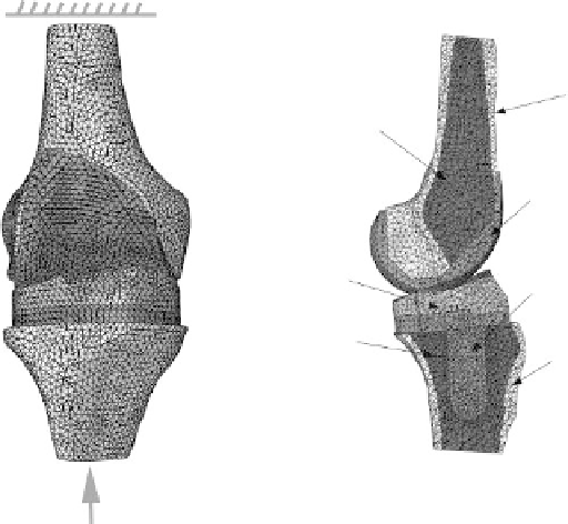
Maintain flexion angle
Femur cortical
Femur trabecular
Femoral component
Tibial component
Tibial tray/insert
Tibia trabecular
Tibial cortical
Applied load
FIgure 8.1
(See color insert.)
Finite element model of the knee implant and bones simulating compression
with flexion.
8.2.2 m
aterial
p
ropertieS
The FE model, as shown in Figure 8.1, consisted of the distal femur and proximal tibia with sec-
tioned trabecular and cortical regions, and the implant, including the femoral component, tibial
insert, and tibial tray. The FE model consisted of about 2.36 million tetrahedral elements and was
idealized with homogeneous material properties. Orthotropic material properties were assigned to
the cortical bone (Ashman et al. 1984). The trabecular bone of the femur and tibia was assigned
with a Young's modulus ranging from half to two times the suggested elastic moduli of 389 MPa
(femoral) and 445 MPa (tibial) (Linde, Hvid, and Pongsoipetch 1989; Rohlmann et al. 1980). The
femoral component and tibia tray of the implant was assigned an elastic modulus and Poisson's ratio
of 110 GPa and 0.34, respectively (Chu 1999), while the ultra-high-molecular-weight polyethylene
(UHMWPE) insert was assigned values of 8.1 GPa and 0.46 (Miyoshi et al. 2002). The coefficient
of friction between the femoral components and the tibial insert was set to be 0.07 (Godest et al.
2002). The implant and bones were tied together. The material properties of the model are sum-
marized in Table 8.1. Because the surgical resection process depended on surgical experience and
the conditions of the patients, the optimal position of the implant and knee was established by a
correlation operation that gave a relative objective alignment. The tibial tray was tilted 10 degrees
posteriorly (Singerman et al. 1996).
8.2.3 B
oundary
and
l
loadinG
c
onditionS
The model was assigned a compressive load of 2000 N on the distal tibia with the proximal femur
restrained (Kim, Kwon, and Kim 2008; Villa et al. 2004). Typical knee examination angles of 0, 5,
30, 45, and 60 degrees of flexion were simulated. The predicted principal compressive stress was
evaluated against the suggested yield to assess the risk of bone yielding failure. Three targeted loca-
tions of interest were identified via stress concentration on the anterior flange (AF), the posterior
supracondylar region (PR), and the screw apex (SR).
Search WWH ::

Custom Search