Hardware Reference
In-Depth Information
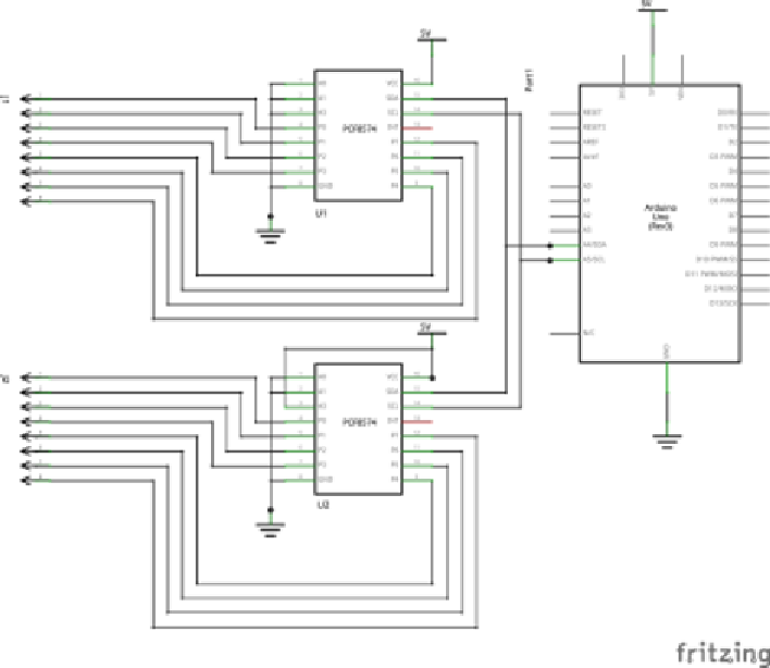
Figure 25-7:
Final schematic (Image created with Fritzing)
Although you can create a shield only from a breadboard example, creating a
schematic does help. Did you notice those INT pins on the integrated circuits?
The PCF8574AP can “warn” a device through an interrupt that one of the inputs
has a changed state. On a breadboard, this was impossible to notice, but on a
schematic, it is clearly visible. It might be a good idea to connect these to the
Arduino in a next version. For now, it is time to create the shield.
Step 3: The PCB
The most rewarding part of creating a shield is designing the PCB, the Printed
Circuit Board. It is also the most complicated part, but it isn't overly difi cult,
and Fritzing helps you a lot.
Designing a PCB is all about the physical world; in the schematic view, it
doesn't matter if the connectors go on the left side or on the right side. It is more
a question of preference, and if I put the connectors on the left, it was mainly


Search WWH ::

Custom Search