Hardware Reference
In-Depth Information
Remember, the PCF8574AP needs to be coni gured by either pulling pins high
or low to dei ne the address. This can either be done “hard” by physically wir-
ing the pins on the shield, or “soft” by placing jumpers on the board. For this
example, they will be hard-wired. You can add headers and jumpers as an
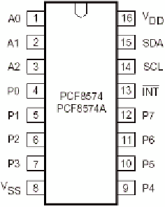
exercise. The pin layout is shown in Figure 25-1.
Figure 25-1:
PCF8574AP pin layout
Open up Fritzing and enter the Breadboard view. By default, a new project
already has a breadboard placed in the center of the view. Go to the Parts panel
and search for the PCF8574AP chip by entering the text “PCF8574” next to the
magnifying glass. The result will be displayed below. To place a component, you
can drag the component from the Component view directly onto the breadboard.
Place the two PCF8574AP chips and headers on the breadboard. Connect +5 V
and GND pins of the Arduino to the power rails of the breadboard, and then
wire power to the integrated circuits.
Pin 16 is V
DD
, supply voltage, and pin 8 is V
SS
, supply ground. This is a com-
mon layout for integrated circuits.
Next, connect the I
2
C bus wires. Remember, pin A4 is for SDA, and A5 is for
SCL. Connect these two pins to the breadboard. Figure 25-2 shows my layout.
Next, set the addresses of the two integrated circuits. Pins 1, 2, and 3 are used
for the address. For this example, device 0 (on the left) will use 000b (all low),
and device 1 (on the right) will use b001; that is, A0 and A1 will be low, and A2
will be high. This can still be achieved without the breadboard view becom-
ing too complicated by using both the top and lower power rails, as shown in
Figure 25-3.


Search WWH ::

Custom Search