Hardware Reference
In-Depth Information
compared to the amount of time spent off—you can adjust the light intensity.
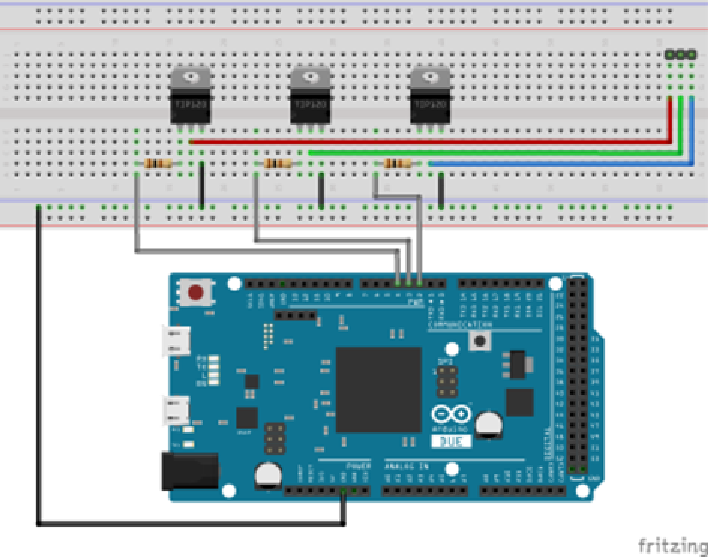
The three transistors will be controlled by pins 2, 3, and 4. The TIP120 transis-
tor is a powerful component that can let through a large amount of current
compared to what the Arduino can provide, or sink. Adafruit's l exi-strip
has four connectors: one for a 12-V power supply, and one for each of the red,
green, and blue components. By connecting these to the
ground
, or 0 V, they
turn on each of the color components. This is what the transistor will be used
for; it will allow as much current through as is required, but since the base
will be connected to PWM, it will turn on and off very quickly, giving the
appearance of dimming.
This device does not have a screen and does not provide any way to let the
user coni gure the timing sequence or when it should start. By default, the
sketch will begin its timing sequence as if the user had connected it at midday.
Figure 19-4 shows the schematic.
Figure 19-4:
Schematic (Image created with Fritzing)


Search WWH ::

Custom Search