Information Technology Reference
In-Depth Information
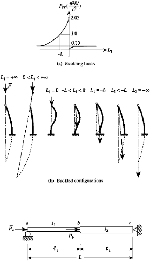
FIGURE 11.32
Buckling loads and buckled configurations. The equivalent columns with hinged ends are shown with dashed
lines.
FIGURE 11.33
A stepped column.
The global transfer matrix is defined by
z
L
=
Uz
a
(1)
with
U
2
U
1
U
=
(2)
where
U
1
is given by Eq. (11.47) with
,EI,
and
N
r
ep
lac
ed
by
1
,EI
1
,
and
P
a
, respectively.
Also,
U
2
+
is g
iv
en
by
Eq. (11.4
7)
using
2
,EI
2
,
and
P
a
P
b
. Note that the axial force
N
in
+
element 2 is
P
a
P
b
, not just
P
b
.
The column is simply supported on both ends, so that the boundary conditions are
w
=
=
w
=
=
M
x
=
a
M
x
=
L
0
(3)
x
=
a
x
=
L


Search WWH ::

Custom Search