Information Technology Reference
In-Depth Information
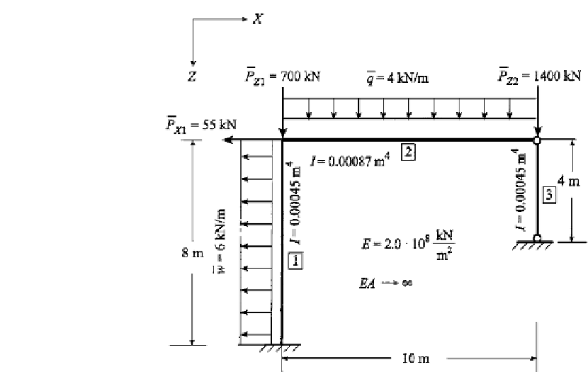
FIGURE 11.19
Geometry and loading of a framework.
EXAMPLE 11.5 System Analysis of a Framework with Second Order Effects
In the previous example, the results of first order and second order calculations are compar-
ed to emphasize the importance of the imperfections on stability behavior. In this example, a
second order analysis of a framework is demonstrated in full detail. Choose the framework
of Fig. 11.19, where it is assumed that the beam elements are rigid with respect to extension.
The calculation procedure of an approximate geometrically nonlinear analysis, including
second order effects, is given in Table 11.5. In the initial integration step, which for practical
problems very often is sufficient, the stress resultants of the linear analysis are taken as
the fundamental state of the stability analysis. For this example, a linear analysis of this
framework gives
N
element1
=−
4kN
,N
element2
=
0
,N
element3
=−
1116
.
2093
.
6kN
.
Load Combinations and Unknowns of the Displacement Method
In addition to the geometric description of the framework, the basic load cases and possible
imperfections have to be selected. Because the superposition of the results of different load
cases does not apply for a nonlinear problem, a specific load combination has to be fixed. We
choose to introduce a factor of safety of 1.5 (see Fig. 11.20). For both the linear and the second
order calculations, the displacement method can be employed as described in Chapter 5
with the global (
X, Y, Z
) and the local
coordinates. Follow the usual procedure of the
displacement method and choose the nodal unknowns as shown in Fig. 11.21, considering
the specific boundary conditions of the problem. In general, three local degrees of freedom
are assigned to each node of this planar system: a horizontal displacement (
U
), a vertical
displacement
(
x, y, z
)
These are either unknown or prescribed by the
boundary conditions, for instance, for node 1 with clamped end conditions all three degrees
of freedom have to vanish, as shown in Fig. 11.21. Because the extensional stiffness
EA
is
assumed to be infinite in all members, the values of the responses of nodes 2 and 3 are not
independent. Hence,
U
2
and
U
3
are equal, and the vertical displacements of nodes 2 and 3
are zero. Due to these assumptions, only two nodal values remain as unknowns:
U
2
and
(
W
)
, and a rotation
().
.
2


Search WWH ::

Custom Search