Information Technology Reference
In-Depth Information
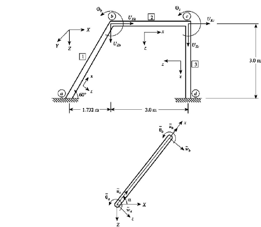
FIGURE 10.2
A plane frame.
The displacement vectors for each element are
w
a
θ
a
u
b
w
b
θ
b
]
T
v
1
=
[
u
a
u
b
w
b
θ
b
u
c
w
c
θ
c
]
T
v
2
=
[
(2)
u
d
w
d
θ
d
]
T
The element stiffness matrices
k
i
in the local coordinate systems, the transformation ma-
trices
T
i
, and the system stiffness matrix
K
are derived in Example 5.5. The corresponding
consistent mass matrices will be derived in this example.
Equations (10.10b and d) give expressions for the element mass matrices corresponding
to translatory [Eq. (10.10b)] and rotary [Eq. (10.10d)] inertia. Represent the sum of these
two mass matrices by
m
i
, the total element mass matrix. For element 1:
u
c
w
c
θ
c
v
3
=
[
1
10
−
4
=
.
732
2
+
3
2
=
3
.
464 m
,
ρ
=
γ
A
=
7800
×
32
×
=
24
.
96 kg
/
m
,
2
I
10
−
2
10
−
5
10
−
4
r
y
=
/
A
=
.
356
×
/
32
×
=
8
.
581
×
m
,
(3)
60
◦
α
=


Search WWH ::

Custom Search