Information Technology Reference
In-Depth Information
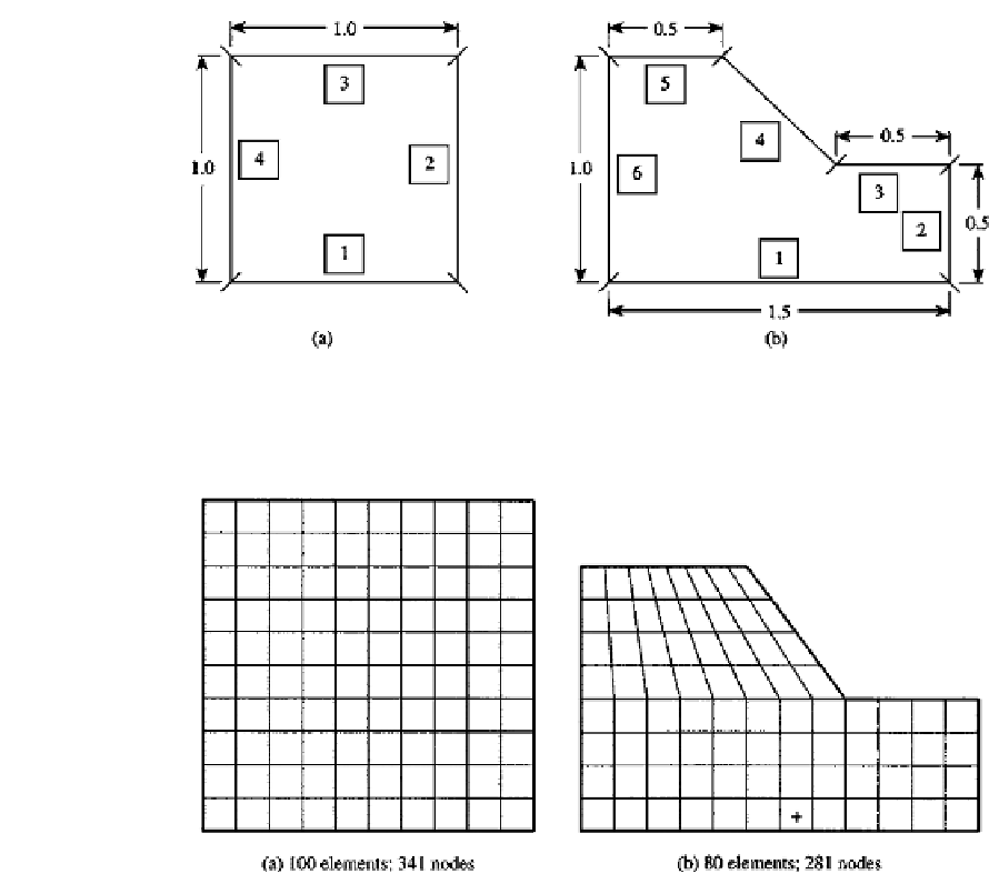
FIGURE 9.14
Cross-sections for Example 9.6.
FIGURE 9.15
Finite element meshes for the cross-sections of Fig. 9.14. All elements are 8-node isoparametric elements.
The integral equation of Eq. (14) of Example 9.2 will be integrated using Gauss quadrature.
The torsional constant and shear stresses are to be calculated.
The results of the computation are compared to the results using finite elements with the
meshes of Fig. 9.15. The elements used are eight node isoparametric elements. The results
of the direct integration and finite elements are shown in Tables 9.1 and 9.2.
It is seen that the integration of the integral equation exhibits good accuracy for the
computation of the torsional constant and stresses. These results converge to the exact
value or the finite element results, although the stress results show some fluctuation in the
process of converging.
The results of direct integration for the square cross-section of Fig. 9.14a are also com-
pared in Table 9.1 to a boundary element solution of the same equation. For the boundary
element solution, constant and linear elements are employed. The number of elements in
each computation is taken to be the same as the number of integration points on the whole
boundary although the locations of the nodes of the elements are different from those of
the integration points. The number of the boundary segments is not necessarily the same as
that of the boundary elements but the size of the system of linear equations is kept the same.


Search WWH ::

Custom Search