Information Technology Reference
In-Depth Information
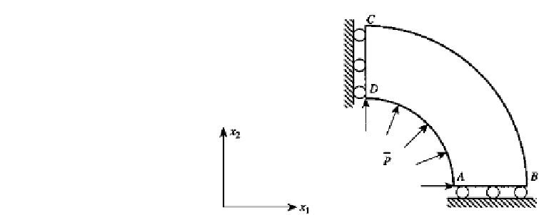
FIGURE 9.9
Modeling of the structure.
The solution of (5) for the two-dimensional plane strain problem takes the form
1
G
r
2
a
i
ln
1
=
=
g
i
i
1
,
2
(7)
π
8
r
Substitute (7) into (4) and note that when the loading takes the form given by (6),
u
i
becomes
u
i
, the fundamental solution. Utilize the relationship of Eq. (9.68) to find the expression for
u
ji
of Eq. (9.74). Follow the procedure from Eq. (9.74) to Eq. (9.78) to obtain the expression
for
p
ji
.
Due to the symmetry of the structure and the loading, only one quarter of the cylinder
needs to be modeled. This is shown in Fig. 9.9. The prescribed boundary conditions are
(Fig. 9.10a):
u
2
=
0
and
p
1
=
0
on side
A
−
B
p
i
=
0
i
=
1
,
2
on side
B
−
C
(8)
u
1
=
0
and
p
2
=
0
on side
C
−
D
p
i
=
pa
i
i
=
1
,
2
on side
D
−
A
Also,
p
Vi
=
0 for this problem. The unknown variables to be calculated are (Fig. 9.10b):
u
1
and
p
2
on side
A
−
B
u
i
i
=
1
,
2
on side
B
−
C
(9)
u
2
and
p
1
on side
C
−
D
u
i
i
=
1
,
2
on side
D
−
A
Use quadratic elements for the boundary discretization. The geometry, displacements,
and tractions are modeled with this kind of element. Substitute the quadratic shape func-
tions of Eq. (9.99) into (1) to obtain Eq. (9.91) and follow the manipulations from Eq. (9.92)
to Eq. (9.94) to form the system equations
HV
=
GP
(10)
Substitute the boundary conditions of (8) into (10) and move all the terms involving un-
known quantities to the left-hand side and all the terms involving known quantities to the


Search WWH ::

Custom Search