Information Technology Reference
In-Depth Information
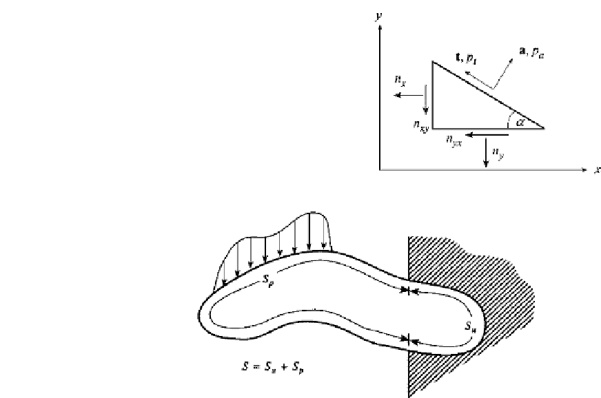
FIGURE 1.11
Surface force conditions for stress resultants
n
x
,n
y
,
n
xy
=
n
yx
for a thin element lying in the
xy
plane.
FIGURE 1.12
The surface
S
of a solid is considered to be made up of two surfaces
S
u
and
S
p
. The symbol
S
u
designates regions
with known displacements, whereas
S
p
denotes everything else, including those portions of the surface where
applied forces occur.
Note that
A
T
is of the same form as
D
T
of Eq. (1.53) in that the derivatives in
D
T
correspond
to the projection directions in
A
T
. Equations (1.57), which are surface stress conditions for
a point on the boundary, are often referred to as Cauchy's formula.
In particular, for the thin, flat element used for plane stress and strain, the surface condi-
tion takes the form (Fig. 1.11)
p
a
p
t
n
x
n
y
n
xy
sin
2
cos
2
α
α
2 sin
α
cos
α
=
(1.59)
sin
2
cos
2
−
sin
α
cos
α
sin
α
cos
α
−
α
+
α
where
n
x
,n
y
,
and
n
xy
=
n
yx
are stress resultants for the thin element, and
p
a
,p
t
are the
tractions normal and tangential to the boundary.
If surface force
s
(per unit area) are applied externally they are referred to as prescribed
surface
tractions
p
. Suppose the whole surface of the body is designated by
S
and that
those portions of the surface with prescribed tractions are designated as
S
p
(Fig. 1.12). Let
the remainder
o
f the surface, i.e.,
S
−
S
p
, be denoted as
S
u
to indicate where prescribed
displacements
u
appear.
Equilibrium requires that the resultant stress
p
be equal to the applied surface tractions
on
S
p
:
p
=
p
on
S
p
(1.60)


Search WWH ::

Custom Search