Information Technology Reference
In-Depth Information
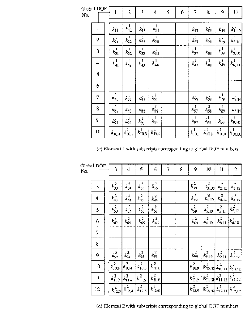
FIGURE 6.15
(continued).
that the
x
and
y
loading components of a node are placed together (this corresponds to the
order of the displacement components in the element stiffness matrix of 2). From Eqs. (6.42)
(or 6.46) and (6.43), the loading vector for the element of Fig. 6.10 would appear as
1
T
2
3
4
p
i
0
p
y
4
]
T
=
p
x
p
y
p
y
p
y
=
[
p
x
1
p
y
1
p
x
2
p
y
2
p
x
3
p
y
3
p
x
4
(4)
p
x
p
x
p
x
p
y


Search WWH ::

Custom Search