Information Technology Reference
In-Depth Information
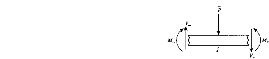
FIGURE 5.2
A short beam segment with concentrated force
P
at
location
j
. Net internal forces and moments just to each
side of
j
are shown. Sign Convention 1 is used.
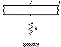
FIGURE 5.3
A beam supported by a spring with stiffness
k
.
is also conti
nu
ous here, i.e.,
M
+
=
M
−
.
Now, sum the vertical forces:
V
−
−
P
−
V
+
=
0or
V
+
=
P
. Thus, it is seen that the shear force changes by a magnitude
P
in moving
across the load. In summary, these relations are
V
−
−
+
−
w
V
M
w
V
M
0
0
=
+
(5.8)
−
P
0
j
j
j
z
j
z
j
=
+
z
j
or in the equivalent transfer matrix form
+
−
1000
.
w
V
M
...
w
V
M
...
0
0100
.
0
0010
.
−
P
=
(5.9)
0001
.
0
... ... ... ... .
...
0000
.
1
1
1
j
j
z
j
z
j
=
U
j
This transfer matrix is often referred to as a
point matrix
to distinguish it from the transfer
matrix for an element of finite length, which is called a
field matrix
.
EXAMPLE 5.1 Point Matrix for Extension Spring
Many point matrices can be derived in a fashion similar to that accounting for a concen-
trated force. Consider a beam supported by an extension spring at
j
(Fig. 5.3). The force
in the spring is proportional to the beam deflection at
j
, i.e., the force is
k
w
j
. The point
matrices of Eqs. (5.8) and (5.9) apply with
V
+
=
V
−
+
k
w
; the sign indicates that the force


Search WWH ::

Custom Search