Information Technology Reference
In-Depth Information
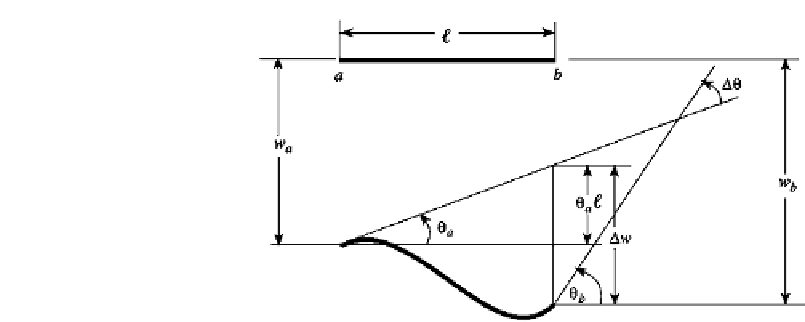
FIGURE 4.2
Geometry of deformation for a beam element.
4.2.2
The Geometry of Deformation
It follows from the geometry of the deformed beam shown in Fig. 4.2 that the deflection
w
θ
and slope
at
b
in terms of these variables at
a
are
.
w
b
=
w
a
−
θ
a
+
w
.
θ
=
θ
+
θ
b
a
(4.4)
.
Rigid body
Deformation
displacements
.
where the deflection
w
and slope
θ
are due to the deformation.
4.2.3 The Material Law
The deformation quantities
w
and
θ
can be determined using the material law rela-
tionships. Suppose the
w
and
θ
terms are separated into the effects of shear force and
bending moment, giving
w
=
w
V
+
w
M
(4.5)
θ
=
θ
V
+
θ
M
Various strength of material methods, such as the energy methods of Chapter 3, can be
employed to find these variables in terms of the bending moment and shear force at some
point along the beam. The resulting expressions are
force-deformation relations
. First the rigid
body motion should be eliminated. To do so, fix the left end of the beam of Fig. 4.2, which
has already undergone rigid body displacements. This gives the configuration of Fig. 4.3a.
Rotate the beam of Fig. 4.3a clockwise an angle
a
about end
a
. Then the beam can be
viewed as a deformed horizontal beam with the left end clamped (Fig. 4.3b). If
θ
w
a
and
θ
a
are now considered to be zero, the quantities
w
and
θ
are the deflection and rotation,
respectively, of the right end. Both
w
and
θ
can be computed using strength of materials
techniques.


Search WWH ::

Custom Search