Environmental Engineering Reference
In-Depth Information
Rise
Run
= Slope
Slope
Rise
(dH)
(dH)
(dL)
= Slope
Run
(dL)
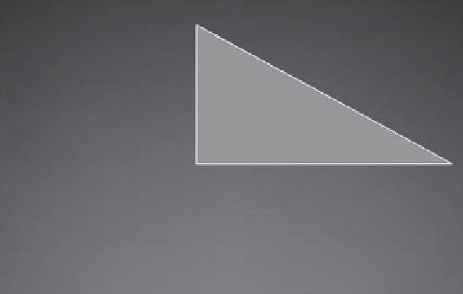
I =hydraulic head=dH/dL
FIGURE 3.31
Calculating the hydraulic head.
This information is needed to determine the general direction of groundwater flow
between the three wells:
• Relative geographic position of the wells
• Distance between the wells
• Elevation of water in each well
Calculating the direction of groundwater flow involves the following steps (Heath 1983),
and an example of the procedure is shown in Figure 3.32:
Well 1
Head= 26.26m
(26.26m)
N
N
(26.26 - 26.20)
(26.26 - 26.07)
=
215
X
X= 68m
26.20m
Contour line
(26.20m)
Well 2
Head= 26.20m
Intermediate head
130m
26.20 - 26.07
130
Hydraulic gradient = 0.001m/m
(26.07m)
Well 3
Head= 26.07m
0
25
50
100
0
25
50
100
Groundwater
flow direction
Scale in meters
Scale in meters
Steps 1 and 2
Steps 3 through 5
FIGURE 3.32
Determining the direction of groundwater flow. (Modified from Heath, R.C.,
Basic Ground-Water Hydrology
,
United States Geological Survey, Water Supply Paper 2220, United States Government Printing Office,
Alexandria, VA, 1983.)


Search WWH ::

Custom Search